
Simple Two-Transistor Motorcycle Alarm
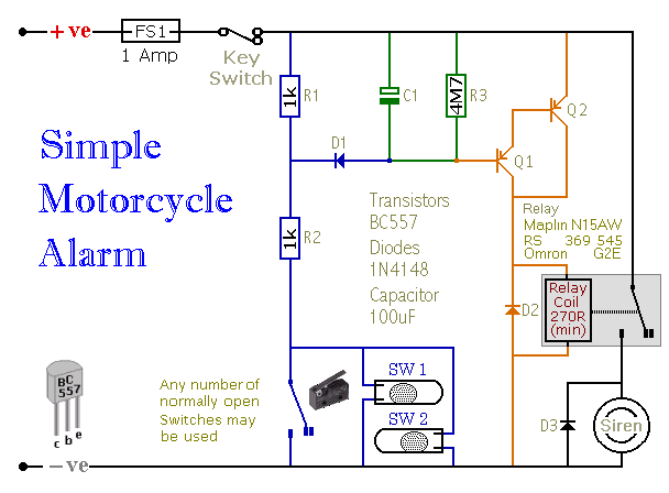
The electronic schematic described employs a straightforward yet effective alarm system utilizing transistors, resistors, capacitors, and diodes. The primary function of this circuit is to activate a relay that sounds a siren upon the closure of a switch, typically triggered by unauthorized movement or tampering with a vehicle.
The circuit begins with the activation of the transistors Q1 and Q2, which are configured in a Darlington pair arrangement to amplify the current from the trigger switch. The use of R1 as a low-value resistor provides a degree of protection against environmental factors such as moisture, ensuring that unintended activation does not occur. R2 serves a dual purpose: it limits the base current to the transistors and controls the charging rate of capacitor C1, which is integral to the latching function of the circuit.
Capacitor C1 is charged quickly through R2 when the trigger switch is closed, enabling the relay to remain energized even after the switch is reopened. This latching mechanism is critical for ensuring that the siren continues to sound for a predetermined duration, which can be adjusted by modifying the values of R3 or C1 as needed. The discharge path for C1 is controlled by D1, which prevents unwanted discharge through R1, maintaining the integrity of the alarm system.
The relay itself is selected based on its coil resistance, which determines the maximum current that flows through Q2. This careful selection ensures that the transistor operates within safe limits while providing sufficient current to activate the relay. The inclusion of diodes D2 and D3 protects the circuit from reverse voltage spikes, a common issue with inductive loads such as relays, thereby safeguarding the overall integrity of the electronic components.
In summary, this alarm circuit is a well-designed system that integrates multiple electronic components to provide a reliable method of alerting users to unauthorized access or movement, with adjustable timing features and protective measures against environmental influences and electrical anomalies.When one of the switches is closed - the base of Q1 is connected to ground through D1 & R2. This switches Q1 on - and it in turn switches Q2 on. Q2 connects the positive side of the relay coil to the supply line. The relay energizes - and the siren sounds. = If R1 had a high value - moisture on the switches might be enough to lower the voltage - a t the junction of R1 & R2 - to the point where Q1 would switch on. Using a 1k resistor for R1 eliminates this problem. = R2 limits the current through the emitter-base junctions of Q1 and Q2. It also controls the speed at which the capacitor charges. C1 is part of the latching circuit that keeps the relay energized after the trigger-switch has been re-opened. I wanted the relay to latch quickly - so that even a brief closing of the trigger-switch would activate the alarm.
That`s why R2 is a 1k resistor. It charges C1 very quickly. = When the trigger-switch is re-opened - it`s the charge stored in C1 that keeps the transistors switched on. So the relay remains energized and the siren continues to sound. It will go on sounding until the charge in C1 falls to a level where it can no longer keep the transistors switched on.
At this point - the relay will drop out and the siren will stop. = How long this takes to happen depends on the size of the capacitor and the value of R3. I selected both - by trial and error - to give a delay of about a minute. There is no point in trying to calculate values. The precise time it takes for the siren to stop depends on the characteristics of the actual components used. If you want to increase the time it takes for the siren to stop - use a larger value capacitor. If you want to decrease the time it takes for the siren to stop - reduce the value of R3. = Q1 & Q2 are wired together to form a Darlington-Pair. A single transistor has a relatively low input impedance. C1 would discharge very quickly through its emitter-base junction. So a very much larger capacitor would be needed to produce a one-minute output. The Darlington-Pair has a very high input impedance. It`s roughly that of the single transistor - squared. In fact it`s so high that it has almost no influence on the rate at which C1 discharges. Consequently, the time it takes for C1 to discharge is controlled almost entirely by the value of R3.
= The low value of R1 offers some protection from the effects of condensation on the trigger-switches. However, R1 has to be prevented from discharging C1. This is the purpose of D1. The diode creates a one-way path. When a trigger-switch connects R2 to ground - D1 allows C1 to charge through R2. However - when the switch is re-opened - D1 prevents C1 from discharging through R1. = The transistors are used to switch the relay on and off. Most of the work is done by Q2. If the relay has a coil resistance of at least 270 ohms - then the maximum current passing through Q2 will be about 12 G· 270 = 45mA.
The BC557 has an Ic(max) of 100mA. There is nothing special about the BC557. Any small transistors with a gain (hfe) greater than 100 and an Ic(max) of at least 100mA should do. But remember that the pin configuration of your transistor may be different from that of the BC557. = Relay coils and some sounders can produce high reverse voltage spikes that will destroy sensitive electronic components. D2 and D3 are there to short-circuit these spikes at source - before they can do any damage. Although there is nothing in the alarm circuit itself that`s likely to be damaged - I have no idea what other electronic equipment might be connected to the same supply.
So I included the two diodes as a precaution. = If the alarm switches are fitted properly - the circuit will reset less than 1 minute after the bike has been returned to its centre-stand or kick-stand. If it`s not returned to one of its stands - and at least one of the trigger-switches remains closed - the siren will continue to sound.
Generally sp 🔗 External reference
Related Circuits

This is the simplest single transistor FM wireless transmitter circuit ever posted in CircuitsGallery. In the field of telecommunications, frequency modulation (FM) transmits information by altering the frequency of a carrier wave based on the message signal. FM utilizes...

The circuit consists of a small PIC microcontroller, assembly program, and a few other parts to detect a switch closure from an open door, window, or manual push button and then dial the cell phone number, and transmit a...
The FM transmitter circuit presented is both stable and simple. With an adaptive antenna, it can achieve a transmission range of approximately 200 meters. This transmitter was developed this year and has yielded positive results. The circuit operates using...
Motorcycle battery charger power supply. Refer to the mentioned page for an explanation of the power supply related circuit diagram. The description of the battery charger indicator: The circuit above enhances the appearance of a simple battery charger, making...
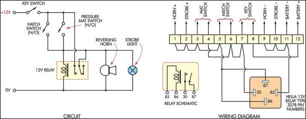
This cost-effective burglar alarm utilizes a 12V strobe light and a truck reversing horn as the visual and audible alarm outputs. The alarm mechanism consists of a 12V horn relay and several pressure mat switches. This straightforward design ensures...
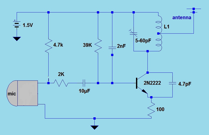
This simple FM (frequency modulation) transmitter is powered only by a 1.5V battery and utilizes a single transistor. The frequency of this transmitter is controlled by the L-C resonance circuit and operates within a range of 80 to 110...