
Simple Touch Alarm circuit

This description outlines a basic touch-activated alarm system. The circuit typically consists of a touch-sensitive sensor, a microcontroller, a sound output device (such as a buzzer or speaker), and a power supply.
The touch-sensitive sensor can be implemented using capacitive or resistive technology, which detects the presence of a finger through changes in capacitance or resistance. Upon detection, the sensor sends a signal to the microcontroller, which processes the input.
The microcontroller is programmed to activate the sound output device for a predetermined duration once the sensor is triggered. This duration can be adjusted in the firmware to suit the application. After the set time elapses, the microcontroller deactivates the sound output, effectively silencing the alarm.
When the sensor is touched again, the process repeats, allowing for multiple activations. The circuit may also include additional features such as LED indicators to provide visual feedback during activation or a reset mechanism to stop the alarm after a certain number of activations.
Power management is crucial in such designs, especially if the device is battery-operated. The circuit can include a low-power mode to conserve energy when not in use. Overall, the schematic for this touch-activated alarm would include the sensor, microcontroller, sound output, power supply, and any additional components for functionality and user interface.Touch the sensor of the alarm with your finger and it starts beeping, goes on for some time and then stops. Touching it again, and it goes again! This litt. 🔗 External reference
Related Circuits

This circuit features a wearer assembly that includes a single lamp, either a 6V6 or 6L6, functioning as both an oscillator and an output amplifier. Coil L1 serves as the medium wave oscillation coil, while coil L2 is composed...

FET several basic bias circuit - self-bias voltage divider circuit The self-bias voltage divider circuit is a fundamental configuration used in Field Effect Transistor (FET) biasing. This circuit employs two resistors to create a stable bias voltage for the transistor's...

This compact water sensor alarm circuit emits a loud warning sound when a humidity sensor detects the presence of water. The circuit utilizes the low-power comparator LM1801 from National Semiconductor. A fixed reference voltage for the integrated circuit is...
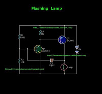
This is a flashing lamp circuit. This circuit operates with a 6V power supply. It can be installed on a bicycle or a car. A common transistor, the 2N3904, is used in this circuit. The flashing lamp circuit is designed...

A 555 timer configured as an astable multivibrator is used in this circuit to generate an audio note. The capacitance value can be changed to vary the audio note as desired. The circuit utilizes a 555 timer IC, which...

Introducing the Cree 1 Watt LED High Power Joule Thief Kit. Joule Thief Simulation II Graph and Schematic. The Cree 1 Watt LED High Power Joule Thief Kit is designed to demonstrate the principles of energy harvesting and efficient power...
Warning: include(partials/cookie-banner.php): Failed to open stream: Permission denied in /var/www/html/nextgr/view-circuit.php on line 713
Warning: include(): Failed opening 'partials/cookie-banner.php' for inclusion (include_path='.:/usr/share/php') in /var/www/html/nextgr/view-circuit.php on line 713