
5W Valve RF Transmitter circuit
As the circuit is tuned into the medium wave range, a larger antenna is required for optimal transmission. A copper conductor is recommended as the antenna, which should be as long as possible and should not have any corners, extending straight and elevated from the ground. One end of the cathode connects to the device while the other connects to the midpoint of the horizontal antenna or one of its ends, ensuring the entire antenna remains contiguous.
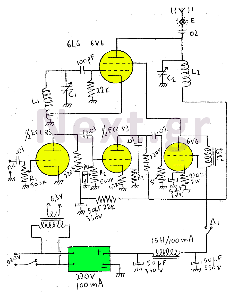
The transmitter amplifier incorporates an ECC83 dual-triode and a 6V6. The configuration features a protective mesh, achieving close to 100% efficiency. The power supply consists of a dry rectifier rated for 220V at 100mA, along with a transformer that has a primary winding of 220V and a secondary winding of 6.3V for heating the lamps. Switch D1 is a single-pole single-action switch that disconnects the high voltage when tuning into other transmitters. With an effective antenna, the transmission range can reach up to 10-15 kilometers.
This circuit design emphasizes the importance of the oscillator-amplifier configuration and the tuning capabilities provided by the variable capacitors. The choice of components, including the 6V6 or 6L6 lamps and the ECC83 dual-triode, plays a critical role in achieving the desired performance characteristics. The design also highlights the significance of antenna length and orientation in enhancing transmission efficiency. The use of a protective mesh configuration in the amplifier maximizes the output while minimizing potential interference. Additionally, the power supply design ensures reliable operation of the circuit, while the inclusion of a switch for high voltage disconnection enhances safety during operation. Overall, this circuit demonstrates a practical approach to medium wave transmission, combining effective component selection with careful attention to antenna design and tuning mechanisms.In this circuit, the wearer assembly consists of only one lamp, 6V6 or 6L6, which acts as an oscillator and as an output amplifier at the same time. Coil L1 is the medium wave oscillation coil. Of 6SA7. The coil L2 consists of 50 spools wrapped on a cylinder covered with a 3 cm diameter insulating material.
The diameter of the wire is 0.5mm. The capacitor C1 is a double variable air of 1000pF (connect the two capacitors in parallel). C1 itself is C2. Through C1 and C2 we tune the transmitter from 2MC to 600KC.
As we tune into the midwaves, the larger the antenna we need to place in the transmitter. For a medium wave antenna we use a copper conductor as long as possible. For the best result, the antenna should not form corners, but extend in a straight line and as high as possible from the ground. One end of the cathode is connected to the device and the other to the middle of the horizontal antenna or to one of the two edges, whereby the whole antenna is contiguous.
The transmitter amplifier consists of the ECC83 dual-triode and 6V6.
The configuration is a protective mesh and is approaching 100%. The power supply uses a dry rectifier 220V for 100mA. We also use a transformer with a primary 220V and a secondary 6.3V to heat the lamps. Switch D1 is single-pole single-action and cuts off high voltage when we want to listen to other transmitters The range of the transmitter with a good antenna reaches 10-15 kilometers.
Related Circuits
This circuit is a wireless car alarm system composed of two modules: a transmitter and a receiver. It operates using FM radio waves and is compatible with vehicles that have a 6-12V DC power supply. If the vehicle's power...
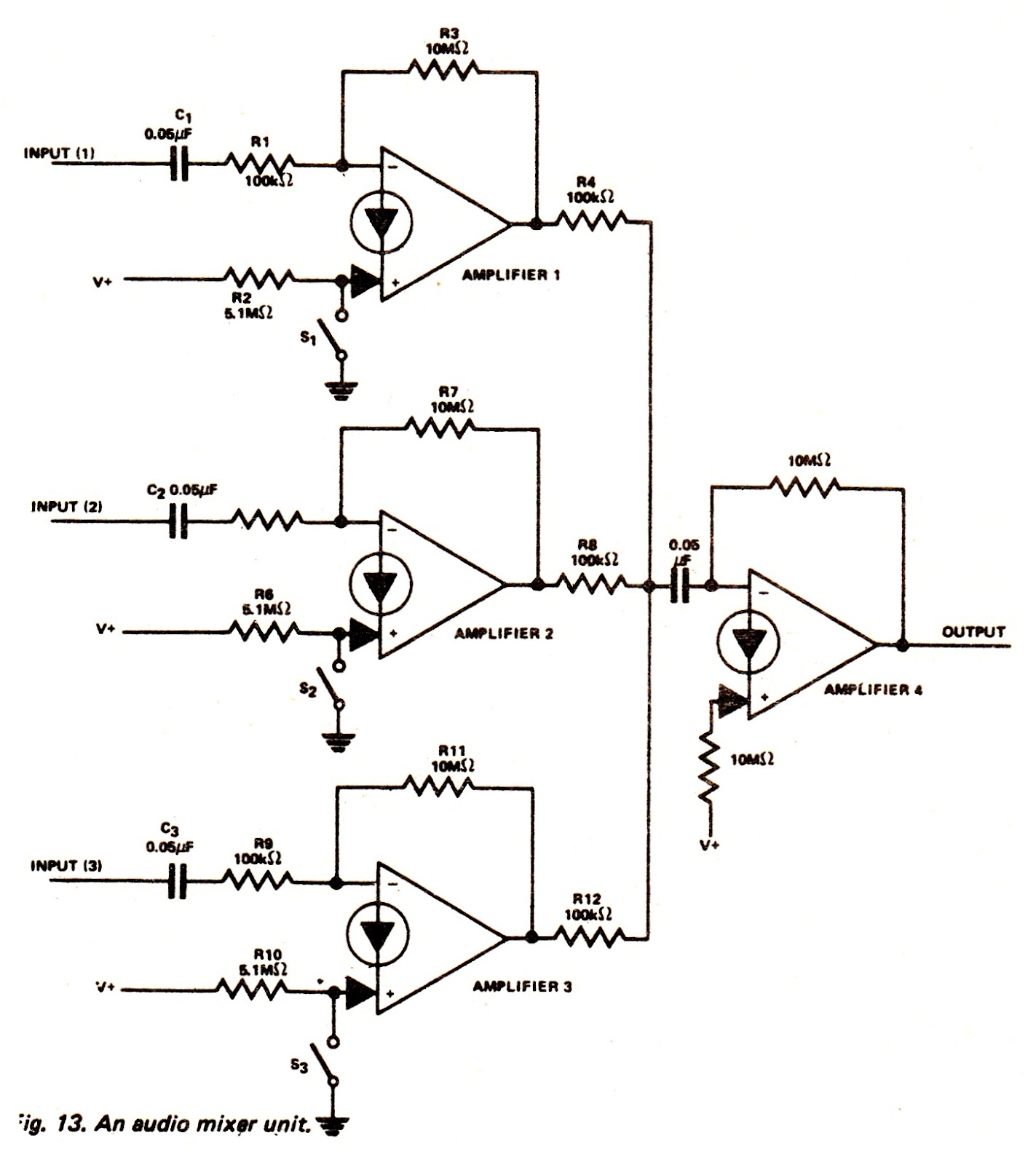
The amplifiers of an LM3900N device can be utilized to create an audio mixer unit that allows for the combination of three separate audio signals into a single composite output. The audio mixer circuit provided operates with a single...
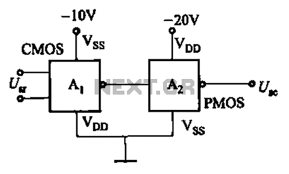
CMOS and PMOS cross interface circuit with PMOS integrated circuit providing high input impedance, allowing the input current to be negligible. The CMOS and PMOS interface circuit is illustrated in the accompanying figure. The CMOS and PMOS cross interface circuit...
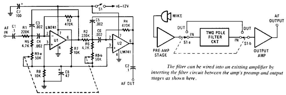
This variable-frequency audio bandpass filter is constructed using two 741 operational amplifiers connected in cascade. The two 741 op amps are configured as identical RC active filters and are cascaded to enhance selectivity. The filter's tuning range spans from...
The circuit is designed for high precision operation over an extended temperature range, provided that V+ remains relatively constant, as the current IZ is dependent on V+. Resistors R1, R2, R3, and R4 are selected to ensure the appropriate...
This circuit is designed to indicate when a plant requires watering. An LED blinks at a low frequency when the soil in the flower pot is excessively dry, turning off as the moisture level rises. The sensitivity of the...
Warning: include(partials/cookie-banner.php): Failed to open stream: Permission denied in /var/www/html/nextgr/view-circuit.php on line 713
Warning: include(): Failed opening 'partials/cookie-banner.php' for inclusion (include_path='.:/usr/share/php') in /var/www/html/nextgr/view-circuit.php on line 713