
Light circuit diagram: Flashing Lamp circuit

The flashing lamp circuit is designed to provide a visual alert through intermittent illumination, making it suitable for use in various applications such as bicycles and vehicles. The circuit operates efficiently at a voltage of 6V, making it compatible with standard battery systems commonly found in these applications.
The core component of this circuit is the 2N3904 NPN transistor, which serves as a switch to control the on-off operation of the lamp. The transistor is chosen for its capability to handle moderate current levels and its availability. The circuit typically includes a resistor connected to the base of the transistor to limit the current and protect it from damage.
A capacitor is also included, which plays a crucial role in determining the flashing frequency of the lamp. By charging and discharging through the resistor and the transistor, the capacitor creates a time delay that results in the flashing effect. The values of the resistor and capacitor can be adjusted to modify the flashing rate, allowing for customization based on user preference or specific application requirements.
To assemble the circuit, the following steps are typically followed:
1. Connect the positive terminal of the 6V power supply to one terminal of the lamp.
2. Connect the other terminal of the lamp to the collector of the 2N3904 transistor.
3. Connect the emitter of the transistor to the ground of the power supply.
4. Connect a resistor from the base of the transistor to the positive terminal of the power supply.
5. Connect a capacitor from the base of the transistor to the ground.
This configuration allows the circuit to operate effectively, providing a reliable flashing indicator for safety and visibility. The simplicity of the design ensures that it can be easily replicated and modified for various applications.This is flashing lamp circuit. This circuit operate with 6V power supply. You can fix this circuit for your bick or for your car. Here I have used common transsistor 2N3904. 🔗 External reference
Related Circuits
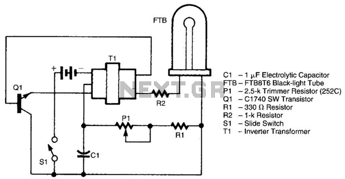
The battery-operated black light utilizes a U-shaped, unfiltered black-light tube, which requires approximately 250 Vac for operation. To generate the 250 Vac from a 6-V battery, the circuit employs a one-transistor blocking oscillator that drives a ferrite inverter transformer....
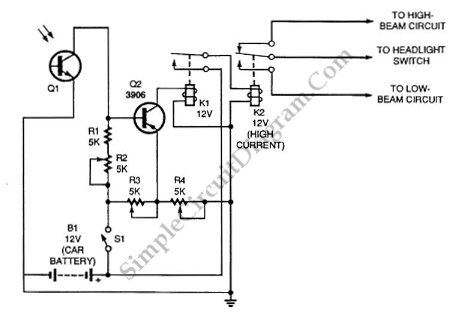
Automatic headlight dimmer circuit diagram for a car's headlight. This circuit ensures maximum brightness for optimal visibility while automatically switching when necessary. The automatic headlight dimmer circuit is designed to enhance driving safety by adjusting the brightness of the vehicle's...
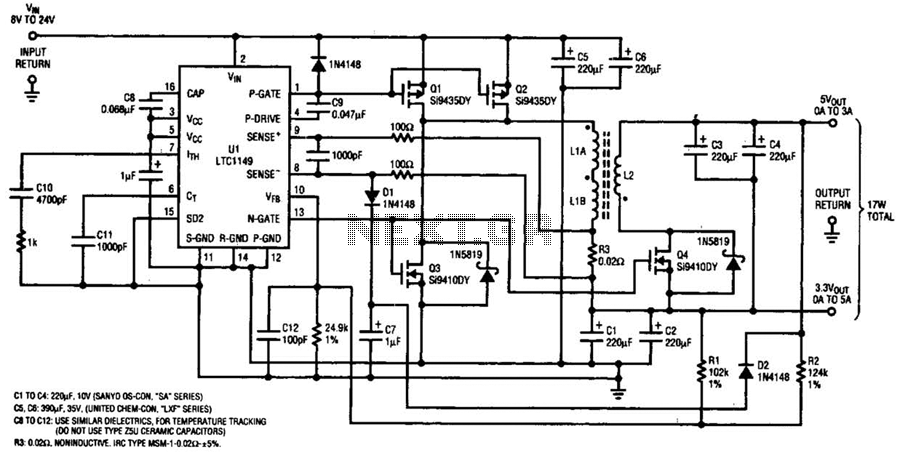
One LTC 1149 synchronous switching regulator can deliver both 3.3 and 5 V outputs. The design's simplicity, low cost, and high efficiency make it a strong contender for portable, battery-powered applications. The circuit described accepts input voltages from 8...

Function: step down the antenna impedance from high to 50 ohms and not, as would be expected, to effect a change from balanced to unbalanced. Component: .. In the context of antenna systems, impedance matching is crucial for maximizing power...

The DAC0832 is a digital-to-analog converter (DAC) chip designed for integration with computer bus systems. It features an 8-bit resolution and operates with a single power supply ranging from 5 to 15 volts. The device is compatible with TTL...
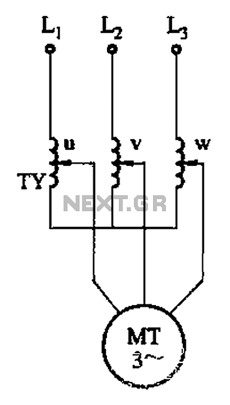
The circuit depicted in Figure 3-176 illustrates an adjustment method that allows the motor to operate at equilibrium. The adjustment range is relatively wide; however, it necessitates a three-phase voltage regulator, which incurs higher input costs. The circuit design in...