
simple tv audio video transmitter
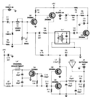
This schematic represents a straightforward yet effective solution for wireless audio-video transmission. The circuit's design emphasizes the importance of component selection and tuning for achieving optimal performance. The use of a Hartley oscillator allows for stable frequency generation, while the modulation stages ensure that both audio and video signals are effectively combined and transmitted. The inclusion of adjustable components, such as potentiometers and optional resistors, provides flexibility for fine-tuning the circuit to meet specific requirements. Proper alignment and setup are crucial for achieving the best results, making this circuit suitable for applications where cable connections are impractical. The range of up to 300 feet makes it a versatile choice for various home entertainment setups, ensuring that users can enjoy their media without the clutter of wires.A very simple TV audio video transmitter circuit can be designed using this schematic diagram. This TV audio video transmitter circuit can be used to transmit video signals from VCR ( or some other device ) to a TV without using any cable. Video signals input at jack J1 are first terminated by resistor R6 and coupled through capacitor C1 to clamp
ing-diode D1. Potentiometer R3 is used to set the gain of the video signal; its effect is similar to that of the contrast control on a TV set. Bias-control R7 can be used to adjust the black level of the picture so that some level of signal is transmitted, even for a totally dark picture.
RF-transformer T1 and its internal capacitor form the tank circuit of a Hartley oscillator that`s tuned to 4. 5 megahertz. Audio signals input at J2 are coupled to the base of Q3 via C2 and R4: the audio signal modulates the base signal of Q3 to form an audio subcarrier thats 4.
5-megahertz higher than the video-carrier frequency. The FM modulated subcarrier is applied to the modulator section through C5 and R9. Resistor R9 adjusts the level of the subcarrier with respect to the video signal. Transistors Q1 and Q2 amplitude modulate the video and audio signals onto an RF-carrier signal. The operating frequency is set by coil L4, which is 3. 5 turns of 24- gauge enameled wire on a form containing a standard ferrite slug. The RF output from the oscillator (L4, C7 and C9 ) section is amplified by Q5 and Q6, whose supply voltage comes from the modulator. Antenna matching and low-pass filtering is performed by C12, C13, and L1. Resistor R12 is optional; it is added to help match the output signal to any kind of antenna. To align this audio video transmitter you need to tune a TV receiver to an unused channel between 2 and 6.
The TV must have an indoor antenna connected irectly to it; an outdoor antenna or cable won`t work. Make sure both otentiometers (R3, R7) are in middle position and apply power to the transmitter. Adjust L4 with a nonmetallic tool until the TV screen goes blank, then fine-adjust L4 for the "most-blank" picture. Connect the video and audio outputs from a VCR(AV source) to jacks J1 and J2 (respectively) of the transmitter.
After that you should see a picture on the TV screen: if you do, readjust L4 for the best picture; if you don`t, check the board for any bad connections. Next, adjust R3 for the best picture brightness and R7 for the best overall picture. Finally, adjust T1 with a nonmetallic tool for the best sound. The TV transmitter combines line level audio and video signals, and transmits the resulting signl up to 300 feet.
The circuit can be powered from a 9-12V power supply circuit. 🔗 External reference
Related Circuits
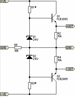
The 22-watt amplifier is straightforward to construct and cost-effective. This circuit can serve as a booster in a car audio system, an amplifier for satellite speakers in a surround sound or home theater setup, or as an amplifier for...
In this circuit, a 74HC14 hex Schmitt trigger inverter is used as a square wave oscillator to drive a small signal transistor in a class C amplifier configuration. The oscillator frequency can be either fixed by a crystal or...
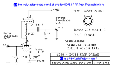
This is one of many available variations for a Symmetrical SRPP Preamplifier based on the 6DJ8 / ECC88 family of tubes. The SRPP circuit has also been referred to as a SEPP, Totem Pole, Mu Follower, Mu amplifier, and...
There will be many occasions when it is beneficial to utilize the P05 supply module sourced from a higher voltage supply. For instance, this could be advantageous when integrating balanced inputs. The P05 supply module is designed to facilitate the...
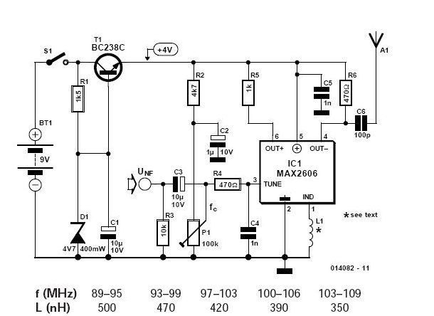
To achieve independence from local radio stations when testing VHF receivers, a frequency-modulated oscillator is required that operates within the range of 89.5 to 108 MHz. However, constructing such an oscillator using discrete components can be quite challenging. Maxim...
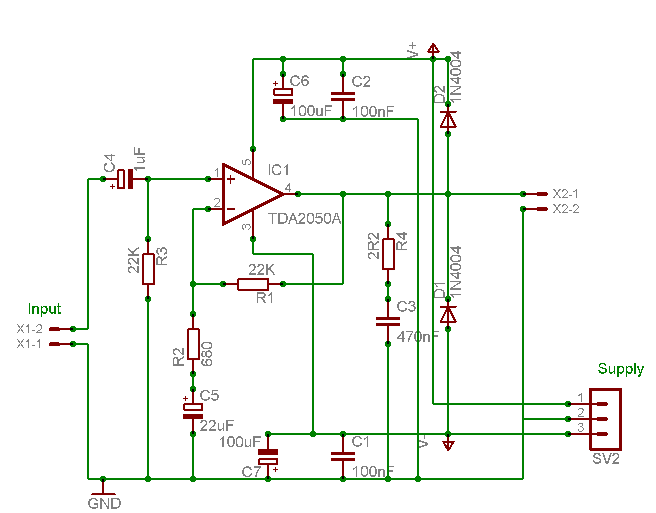
A careful examination of the amplifier photos reveals that the heatsink on the HY60 near-clone built using the TDA2050A is slightly shorter than that of the original HY60s. This unit is positioned at the rear of the amplifier, creating...