
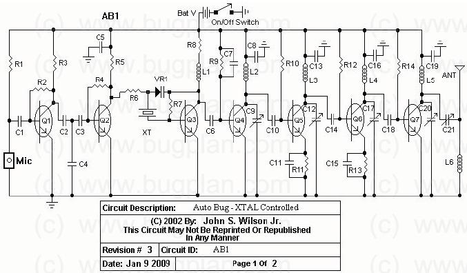
AM Broadcast Transmitter schematic
The circuit utilizes a 74HC14 hex Schmitt trigger inverter, which is a CMOS device known for its ability to convert slow or noisy signals into clean digital signals. In this application, it functions as a square wave oscillator, generating a continuous waveform that drives a small signal transistor configured in a class C amplifier arrangement. The oscillator's frequency can be set either by a crystal oscillator for stability or by using a variable frequency oscillator (VFO) setup, which includes a 100pF capacitor and a resistor network, allowing for frequency adjustments based on user requirements.
The amplitude modulation is achieved through a secondary transistor, which modulates the DC voltage supplied to the output stage. This modulation allows for varying the amplitude of the output signal while maintaining a constant frequency. The output stage is designed to operate with a bias point set to approximately half of the supply voltage (6 volts), ensuring that the amplifier operates efficiently and delivers the desired output without modulation.
To match the output stage to the antenna, a variable capacitor ranging from 30 to 365 pF is employed. This tuning capacitor allows for impedance matching, optimizing the power transfer to the antenna. When properly tuned, the output stage can deliver approximately 20 mA of current through the antenna lead, particularly effective at frequencies near the upper end of the broadcast band, around 1.6 MHz.
The antenna used in this circuit is a dipole antenna approximately 9.8 feet in length, which is compliant with FCC regulations for low-power transmission. The antenna's design and dimensions are critical for ensuring efficient radiation of the signal. The circuit's output power is estimated to be around 40 microwatts, with a range of approximately 80 feet under optimal conditions.
A 'grain of wheat' lamp serves as a visual indicator of the antenna current, helping to achieve the best tuning settings. The inductor used in the circuit is designed with a specific inductance of 140 µH, created by winding 120 turns of #28 copper wire around a 2-inch length of PVC pipe, further contributing to the circuit's performance.
Radiated power can be mathematically approximated using the antenna's radiation resistance and the square of the antenna current. For a dipole antenna with a length less than 1/4 wavelength, the radiation resistance can be calculated, allowing for precise estimation of the radiated power, which is crucial for understanding the circuit's transmission capabilities.In this circuit, a 74HC14 hex Schmitt trigger inverter is used as a square wave oscillator to drive a small signal transistor in a class C amplifier configuration. The oscillator frequency can be either fixed by a crystal or made adjustable (VFO) with a capacitor/resistor combination.
A 100pF capacitor is used in place of the crystal for VFO operation. Amplitude modulation is accomplished with a second transistor that controls the DC voltage to the output stage. The modulator stage is biased so that half the supply voltage or 6 volts is applied to the output stage with no modulation.
The output stage is tuned and matched to the antenna with a standard variable 30-365 pF capacitor. Approximately 20 milliamps of current will flow in the antenna lead (at frequencies near the top of the band) when the output stage is optimally tuned to the oscillator frequency. A small 'grain of wheat' lamp is used to indicate antenna current and optimum settings. The 140 uH inductor was made using a 2 inch length of 7/8 inch (OD) PVC pipe wound with 120 turns of #28 copper wire.
Best performance is obtained near the high end of the broadcast band (1.6 MHz) since the antenna length is only a very small fraction of a wavelength. Input power to the amplifier is less than 100 milliwatts and antenna length is 3 meters or less which complies with FCC rules.
Output power is somewhere in the 40 microwatt range and the signal can be heard approximately 80 feet. Radiated power output can be approximated by working out the antenna radiation resistance and multiplying by the antenna current squared.
The radiation resistance for a dipole antenna less than 1/4 wavelength is R = 80*[(pi)^2]*[(Length/wavelength)^2]*(a factor depending on the form of the current distribution) The factor depending on the current distribution turns out to be [(average current along the rod)/(feed current)]^2 for short rods, which is 1/4 for a linearly-tapered current distribution falling to zero at the ends. Even if the rods are capped with plates, this factor cannot be larger than 1. Substituting values for a 9.8 foot dipole at a frequency of 1.6 MHz we get R= 790*.000354*.25 = .07 Ohms.
And the resistance will be only half as much for a monopole or 0.035 Ohms. Radiated power at 20 milliamps works out to about I^2 * R = 14 microwatts. 🔗 External reference
Related Circuits
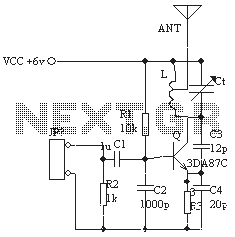
The ordinary triode 3DA87C is utilized to create a long-range FM transmitter circuit, which functions as a standard three-point oscillator circuit. This remote transmitter circuit is capable of large current emissions, achieving a range of up to 1 kilometer...
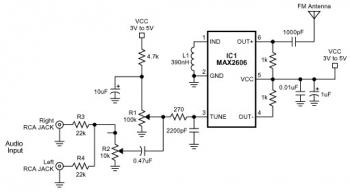
The FM transmitter circuit is built using a single MAX2606 chip. This simple FM transmitter connects a home entertainment system to a portable radio, allowing music to be played in one room and listened to in another, such as...

This design outlines a tracking transmitter for audio tones operating in the FM band frequency. The circuit can function as either a signal transmitter or a remote control transmitter and utilizes only readily available components. It has a transmission...
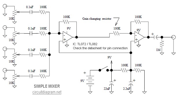
This is a simple mixer featuring four inputs and two operational amplifiers (op-amps). It is designed for mixing microphones or effects outputs. The overall gain from input to output is unity when the potentiometer associated with the input is...
This circuit operates between 150 to 165 MHz. The crystals used are Digi-Key Electronics Barrel Crystals of the CA-301 type, which are relatively inexpensive. Any fundamental crystal with a frequency between 14 and 17 MHz can produce an output...
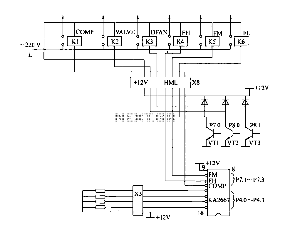
The driving circuit depicted in Figure 18-12 consists of a connection between the driving portion, the microcontroller, and the air conditioning operation components of the bridge. The microcontroller's digital signal levels from ports P4.0 to P4.3 (approximately 12 feet)...