
Simple UHF Video Transmitter
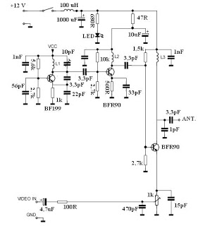
The video transmitter circuit is designed to operate within the UHF frequency range, which is suitable for various video transmission applications. The operating frequency of 470-580 MHz allows for clear transmission with minimal interference, making it ideal for remote video monitoring or broadcasting. The effective range of 30 to 100 meters is contingent upon the quality of the cable used, with shorter cables generally providing better signal integrity.
To enhance the transmitter's performance, particularly in environments with potential signal degradation, the integration of a bandpass filter is critical. This filter will ensure that only the desired frequency range is amplified, thereby reducing the likelihood of noise and interference from other signals. The supply voltage requirement of 9-15 volts allows for flexibility in power source selection, accommodating both standard power supplies and battery options. Utilizing a 9V battery can provide a convenient and portable solution, while a switching power supply may offer improved efficiency and lower noise levels.
When assembling the circuit, attention must be paid to the coil dimensions, as these are pivotal in determining the operational frequency of the transmitter. The coil acts as an inductor that resonates at the desired frequency, and its size and number of turns directly influence the inductance value. Careful calculations and adjustments may be necessary to ensure that the coil is properly tuned to the operating frequency, which will ultimately affect the quality and range of the transmitted signal.
In summary, this video transmitter circuit is a versatile solution for UHF video transmission, requiring careful consideration of component specifications and configurations to achieve optimal performance.Here`s video transmitter circuit is working on the UHF channel frequency 470-580 MHz channel 21-34. This video transmitter can radiate as far as 30-100 meters by using a cable 10-20 cm. If you have a plan to amplify this video transmitter`s signal, please make a good bandpass filter. This video transmitter requires supplies voltage of 9-15 volt. H owever, you can also use a 9v batteries. Better result on low signal noise, use switching power supply. This is an important thing to remember for building of the video transmitter circuit is that the dimensions of coil size to match the frequency of the desired work. The value of the spindle is making coil as follows: 🔗 External reference
Related Circuits
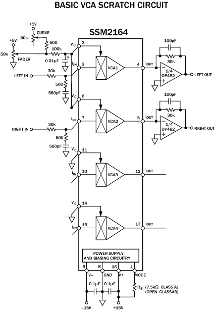
The cut on a fader is fundamentally different from a transform. It is not an instantaneous on/off switch; rather, it features a gradual slope that can range anywhere from a few hundred microseconds to tens of milliseconds. This duration...
This circuit is a simple series tone control circuit utilizing the OP-Amp LM301A. The JFET 2N3684 provides high input impedance and low noise characteristics for the feedback buffer in the op-amp-based tone control. The tone control circuit described employs an...
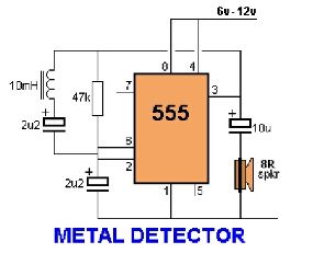
Assemble the circuit on a perfboard or PCB, excluding the inductor. Attach two long wires in place of the inductor. Use a long rod and position the inductor. The circuit assembly begins with the preparation of a perfboard or printed circuit...
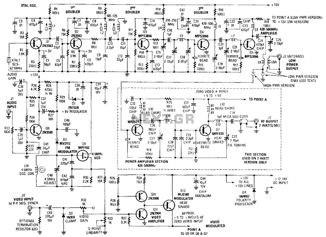
Although the unit was designed for 2 W operation, the Q6 and Q7 stages and their associated components can be omitted. Approximately 1 to 30 mW of RF can be obtained by link coupling to L9. A complete set...
This compact single-chip circuit is designed for measuring the level of electrically conductive fluids or liquids. It functions as a voltage level sensor and employs an AC bias supply to prevent electrolysis of the probes, thereby enhancing their lifespan....
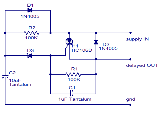
The circuit diagram presented is of a straightforward DC power delay circuit utilizing a silicon-controlled rectifier (SCR). This circuit is quite useful and can be applied in various scenarios. The operation of this circuit is uncomplicated. Upon the application...
Warning: include(partials/cookie-banner.php): Failed to open stream: Permission denied in /var/www/html/nextgr/view-circuit.php on line 713
Warning: include(): Failed opening 'partials/cookie-banner.php' for inclusion (include_path='.:/usr/share/php') in /var/www/html/nextgr/view-circuit.php on line 713