
Simple VOX Circuit
The VOX (Voice Operated Switch) circuit functions by detecting sound levels and activating a connected device when the sound exceeds a predetermined threshold. This is particularly useful in applications where hands-free operation is desired, such as in broadcasting or communication systems.
The primary components of a VOX circuit include a microphone, an amplifier, a threshold detector, and a switching mechanism. The microphone captures audio signals, which are then amplified to a suitable level for processing. The amplified signal is fed into a threshold detector, which compares the audio signal against a reference voltage set by the volume potentiometer.
When the audio signal surpasses the set threshold, the detector activates the switching mechanism, which can control various devices, such as a transmitter or a recording device. The volume potentiometer allows the user to adjust the sensitivity of the VOX circuit, ensuring optimal performance in varying noise environments.
Additional features may include adjustable delay times to prevent unintentional activation from brief or low-level sounds and LED indicators to provide visual feedback on the switch's status. The design may also incorporate noise filters to enhance performance by reducing the impact of background noise.
Overall, the VOX circuit enhances user convenience and efficiency by enabling voice-activated control in various electronic devices, simplifying operation and improving accessibility.VOX is a voice controlled switch, used often for microphones replacing the classic switching button. The actuating threshold is set thru the volume potenti.. 🔗 External reference
Related Circuits
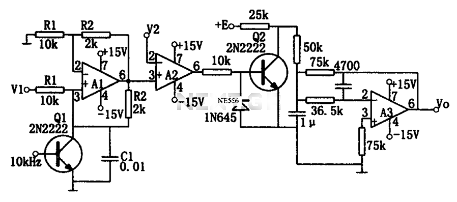
As illustrated in the dividing circuit diagram, A1 consists of a voltage-controlled current source, A2 functions as a voltage comparator, and A3 is configured as an active low-pass filter. When the time constant R1C1 is equal to the clock...
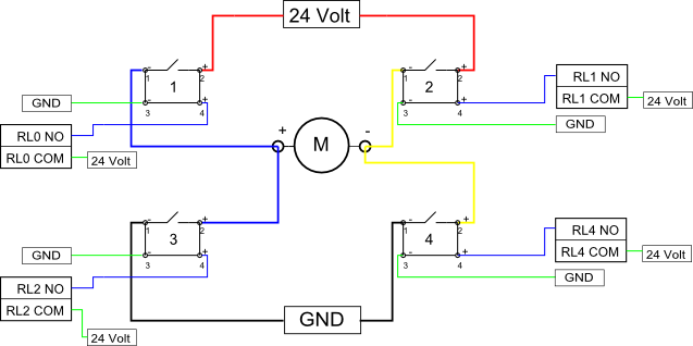
Eight solid-state relays (SSR) and an ADAM-4068 (Serial-I/O device) are utilized to wire a circuit for controlling a motor in a robotic application. The ADAM-6048 is a versatile device that facilitates control of digital inputs and outputs via RS-485...
The schematic diagram is straightforward. SW1 is a pushbutton used to start the timer. The outputs are set to logic level 0 when the timer is inactive and to logic level 1 when the timer is triggered. The relay...
A simple square wave oscillator can be created using two gates from a CMOS 4011 NAND chip. Alternatively, a CMOS 4001 chip or a TTL equivalent can also be utilized. In this circuit, the mark-space ratio can be independently...
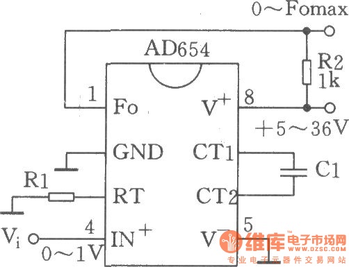
The circuit depicted is a low-cost voltage frequency converter (VFC) utilizing the AD654 component. By connecting the required components, Rl and Cl, as shown in the figure, a functional VFC application circuit can be established. The supply voltage can...

This circuit diagram represents a logic probe based on a single CMOS integrated circuit (IC). The logic probe indicates three conditions: High, Low, and Pulsing. Additionally, no LEDs will illuminate when the probe input is in a high-impedance state,...