
Simple Water Detector Circuit
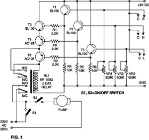
The water detector circuit is designed for reliable operation in various environments where moisture detection is necessary. The use of alternating voltage serves to minimize the risk of corrosion on the electrodes, extending the lifespan of the components. The circuit's core consists of two Schmitt triggers, N1 and N2, which are responsible for generating and processing the AC signal.
The first stage, featuring N1, produces an oscillating output that drives the diodes D1 and D2. These diodes are configured to rectify the AC signal, allowing only the positive half-cycles to charge the capacitor C4. The capacitor serves as a voltage storage element, and its charging behavior is critical for the operation of the relay.
Once the voltage across C4 exceeds the threshold voltage of the second Schmitt trigger, N2, the output changes state, activating the relay. This relay is typically used to control a larger load, such as a drain pump, which is essential for applications like sump pumps or automatic irrigation systems. The functionality ensures that the pump operates only when water is detected, preventing unnecessary energy consumption and potential damage from running dry.
The circuit also features a feedback mechanism that ensures the relay is deactivated when the electrodes lose contact with the liquid. This is crucial for preventing false positives and ensuring the system operates efficiently. Overall, the design is both efficient and effective for applications requiring reliable water detection, showcasing the integration of simple components to achieve a practical solution.This simple water detector circuit uses alternative voltage in order to prevent the corrosion of the electrodes. It is easy to build and uses N1 as a trigger Schmitt gate which generate the AC. If between the electrodes is a electricity conductor, for example an aqueous solution, then because of the rectification action of D1 and D2, the C4 capaci
tor is charging. When the capacitor voltage reaches switching threshold of the N2 trigger Schmitt, the relay will trigger and connect, for example a drain pump. The pump will be disconnected as soon as the electrodes won`t touch the liquid. 🔗 External reference
Related Circuits
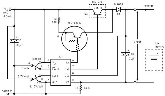
Lithium-ion charger circuit design electronic project using LM3632 controller. The lithium-ion charger circuit utilizing the LM3632 controller is designed to efficiently charge lithium-ion batteries while ensuring safety and longevity. The LM3632 is a highly integrated, step-down linear charger specifically tailored...
Below are three examples of controlling a relay from the PC's parallel printer port (LPT1 or LPT2). Figure A shows a solid-state relay controlled by one of the parallel port data lines (D0-D7) using a 300-ohm resistor and a...

This circuit is an active filter designed for subwoofers, featuring a 24 dB per octave Bessel filter with a cutoff frequency of 200 Hz. It is suitable for those interested in experimenting with audio circuits in the subwoofer frequency...
This circuit should be connected prior to the amplifier circuit. To achieve optimal performance, it is recommended to utilize high-quality electronic components such as metal film resistors, MKM capacitors (non-polar), and tantalum capacitors (bipolar). The power supply module can...
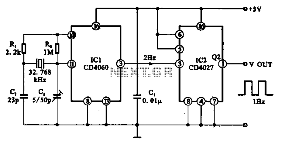
A 1Hz clock signal generator circuit is presented, which demonstrates a sophisticated clock signal generating mechanism. This circuit can be utilized for digital clocks and timing applications. It comprises a binary counter (CD4060), a JK flip-flop (CD4027), and a...

At the input of the operational amplifier, a resistor-diode network can be constructed to create a square-law function conversion circuit. This resistor-diode network acts as a voltage divider, where the input voltage variations lead to different partial pressures. The...