
Simplest lamp flasher circuit
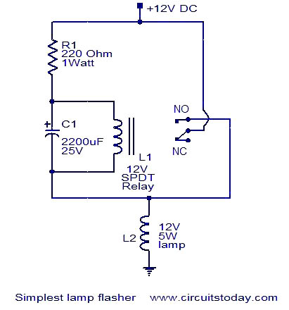
The lamp flasher circuit operates based on the principles of capacitance and relay switching. The capacitor (C1) plays a crucial role in determining the timing of the flashing effect. The resistor limits the charging current to the capacitor, thereby controlling the rate at which the capacitor charges. The value of the resistor (R) and the capacitor (C1) can be selected to adjust the time duration for which the lamp remains lit and the time duration for which it is off, thus altering the flash rate.
When the circuit is powered, the capacitor begins to charge through the resistor. The charging time is defined by the RC time constant, which is calculated as τ = R × C. This time constant dictates how quickly the voltage across the capacitor rises. Once the voltage across C1 reaches the relay's activation threshold, the relay coil is energized, closing the normally open contacts and allowing current to flow to the lamp.
As the capacitor continues to charge, the relay remains activated, and the lamp stays illuminated. Eventually, the capacitor reaches its maximum charge and begins to discharge. The discharge occurs through the load or any path provided in the circuit. As the voltage across the capacitor drops below the relay's release voltage, the relay deactivates, opening the circuit and turning off the lamp.
The cycle repeats as long as power is supplied to the circuit, creating a flashing effect. The frequency of the flashing can be adjusted by changing the values of the resistor and capacitor, allowing for customization based on the desired application. This simple yet effective design is commonly used in decorative lighting, signaling devices, and various low-power applications where a visual alert is needed.This is a very simple lamp flasher circuit that uses only three components (a capacitor, relay and one resistor) other than the lamp. The working of the circuit is very straight forward. When the power is switched ON the capacitor C1 charges through the resistor. When the voltage across the capacitor is sufficient, the relay switches ON and the la mp connected via the normally open contact of the relay glows. The relay remains energized until the capacitor discharges and then the lamp extinguishes. The charging and discharging cycle of the capacitor gives a flashing effect to the lamp. 🔗 External reference
Related Circuits

This design circuit is used to activate circuitry and an analog meter for sensitive DC current measurements. A subsequent inquiry raised the possibility of measuring AC microamperes, which inspired the idea for this circuit. The circuit is designed to facilitate...
This circuit utilizes a photoelectric coupler to achieve 100GΩ isolation between a TTL (Transistor-Transistor Logic) circuit and a relay circuit. This configuration effectively prevents relay noise and peak voltage from affecting the TTL circuit. When the TTL input signal...
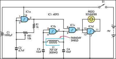
The circuit incorporates two oscillators, both operating at about 40kHz. The first, IC1a, is a standard CMOS oscillator with its frequency adjustable via VR1. The frequency of the second, IC1b, is highly dependent on the inductance of coil L1,...

The BFP640 transistor is utilized for 1575 MHz Global Positioning Satellite (GPS) applications, specifically as a Low Noise Amplifier (LNA). The design objectives include a minimum gain of 16 dB, a noise figure of less than 0.6 dB, an...
The FM telephone circuit is constructed on a compact PC board that can be easily integrated into the housing of a telephone, functioning as a pseudo-speak earphone. This FM circuit connects in series with the telephone line, drawing power...

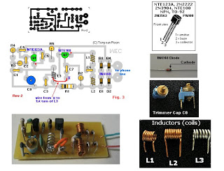
The transmitter utilizes a 6BW6 vacuum tube to achieve an output power of approximately 5 watts. The circuit includes a component CI that is calibrated to produce the cleanest continuous wave (CW) note. The tuning capacitors C8 and C9...