
Sinewave Generator schematics
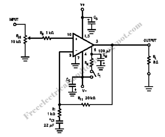
More: The op-amp based phase shift oscillator is much more stable than the single transistor version since the gain can be set higher than needed to sustain oscillation and the output is taken from the RC network which filters out most of the harmonic distortion. The sinewave output from the RC network is buffered and the amplitude restored by the second (top) op-amp which has gain of around 28dB. Frequency is around 600 Hz for RC values shown (7.5K and 0.1uF) and can be reduced by proportionally increasing the network resistors (7.5K). The 7.5K value at pin 2 of the op-amp controls the oscillator circuit gain and is selected so that the output at pin 1 is slightly clipped at the positive and negative peaks. The sinewave output at pin 7 is about 5 volts p-p using a 12 volt supply and appears very clean on a scope since the RC network filters out most all distortion occurring at pin 1.
The described circuits implement methods for generating low-frequency sine waves using phase shift techniques. The first circuit utilizes a transistor, specifically a 3904 NPN transistor, configured in a phase shift oscillator arrangement. The oscillator relies on an RC network that achieves a total phase shift of 360 degrees, allowing for sustained oscillation. The output from the collector of the transistor is buffered by a JFET, providing a low impedance output suitable for driving subsequent stages. The gain of this circuit is crucial; it must be finely tuned by adjusting a 500-ohm resistor to minimize distortion and stabilize the waveform. However, due to the sensitivity of the gain adjustment, this configuration is not ideal for practical applications.
In contrast, the op-amp based phase shift oscillator presents a more stable alternative. This circuit employs operational amplifiers to create a feedback loop that sustains oscillation with a higher gain than necessary, thus enhancing stability. The output is derived from the RC network, which effectively filters out harmonic distortion, resulting in a cleaner sine wave. The configuration uses a resistor of 7.5K ohms and a capacitor of 0.1 µF, yielding an oscillation frequency of approximately 600 Hz. The gain of the second op-amp is set to around 28 dB, allowing the output to be restored to the desired amplitude. The resistor at pin 2 of the op-amp is critical for controlling the oscillator gain, selected to ensure that the output at pin 1 is slightly clipped at both peaks. With a 12-volt supply, the sine wave output at pin 7 measures about 5 volts peak-to-peak, exhibiting a clean waveform on an oscilloscope, thanks to the effective filtering characteristics of the RC network. Overall, the op-amp circuit offers a more robust solution for generating low-frequency sine waves compared to the transistor-based approach.The two circuits below illustrate generating low frequency sinewaves by shifting the phase of the signal through an RC network so that oscillation occurs where the total phase shift is 360 degrees. The transistor circuit on the right produces a reasonable sinewave at the collector of the 3904 which is buffered by the JFET to yield a low impedance output.
The circuit gain is critical for low distortion and you may need to adjust the 500 ohm resistor to achieve a stable waveform with minimum distortion. The transistor circuit is not recommended for practical applications due to the critical adjustments needed.
The op-amp based phase shift oscillator is much more stable than the single transistor version since the gain can be set higher than needed to sustain oscillation and the output is taken from the RC network which filters out most of the harmonic distortion. The sinewave output from the RC network is buffered and the amplitude restored by the second (top) op-amp which has gain of around 28dB.
Frequency is around 600 Hz for RC values shown (7.5K and 0.1uF) and can be reduced by proportionally increasing the network resistors (7.5K). The 7.5K value at pin 2 of the op-amp controls the oscillator circuit gain and is selected so that the output at pin 1 is slightly clipped at the positive and negative peaks.
The sinewave output at pin 7 is about 5 volts p-p using a 12 volt supply and appears very clean on a scope since the RC network filters out most all distortion occurring at pin 1. 🔗 External reference
Related Circuits
This circuit generates sine, square, and triangle waves ranging from 0.1 Hz to 1 MHz. It includes a counter that measures the frequency of the function generator or an external signal with a peak-to-peak voltage of a few volts,...
Any stepper motor can be utilized as a generator. Unlike other types of generators, a stepper motor generates a significant induced voltage even at low rotational speeds. A stepper motor operates by converting electrical energy into mechanical motion through a...
This circuit is a modified version of a function-generator circuit. It features a battery-powered sine wave generator that can be continuously adjusted from 100 Hz to 10 kHz. The described circuit utilizes a sine wave generator to produce a continuous...
This is a design circuit for a simple function generator. Built around a single 8038 waveform generator IC, this circuit produces sine, square, or triangle waves from 20Hz to 200kHz in four switched ranges. There are both high and...
The schematics on this page are provided strictly for educational purposes. If anyone intends to use these designs for profit, they are required by law to obtain permission from the legal owner(s) of the design and comply with any...

The circuit employs a field-effect transistor (FET) at the input of a Schmitt trigger, allowing the use of a low-value capacitor. The trigger, controlled by Q1 and O2, exhibits a hysteresis of approximately 3V, regulated by a 3V zener...