
Single Alarm Circuit
The single alarm circuit is designed to provide security and safety through various features that enhance its functionality. The automatic exit and entry delays allow users to leave and enter the protected area without triggering the alarm immediately, providing a grace period for disarming the system. The timed bell cut-off feature ensures that the alarm will sound for a predetermined duration, preventing it from ringing indefinitely and reducing the likelihood of nuisance alarms.
The system reset function allows users to easily reset the alarm system after it has been triggered, enabling quick restoration of the security status. The circuit accommodates both normally open (NO) and normally closed (NC) configurations, providing flexibility in sensor integration. Normally open contacts will complete the circuit when activated, while normally closed contacts will break the circuit when activated, allowing for a variety of sensor types to be used, such as door contacts and motion detectors.
The schematic for this circuit typically includes a microcontroller or timer IC to manage the timing functions, along with relay outputs to control the alarm sounder and other connected devices. The power supply section ensures that the circuit operates reliably, often incorporating voltage regulation to protect sensitive components. Additionally, a visual indicator, such as an LED, may be included to provide a status signal for the system, indicating whether it is armed or disarmed.
Overall, this alarm circuit design effectively combines essential security features with user-friendly operations, making it suitable for residential and commercial applications.Here is single alarm circuit. The circuit features automatic exit and entry delays, timed bell cut-off and system reset. It has provision for normally open and. 🔗 External reference
Related Circuits
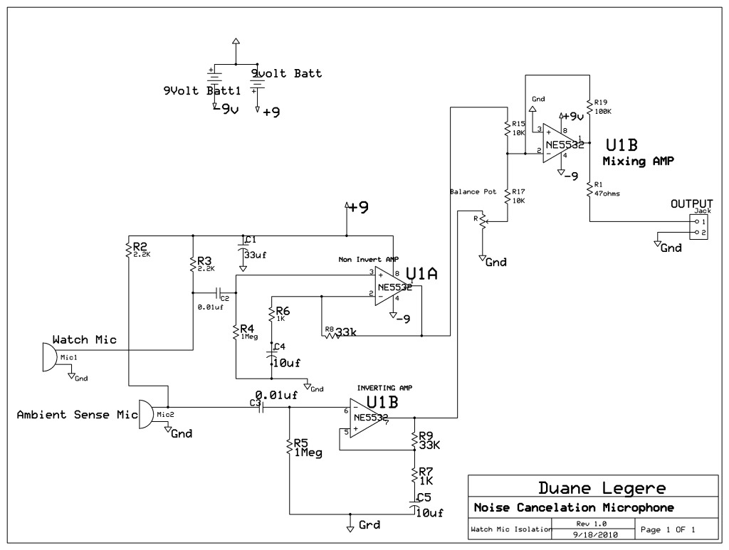
A microphone is designed to listen to a wristwatch while canceling ambient noise in the room. A circuit has been included, which is based on a headphone cancellation circuit. The schematic will be provided shortly. The suggested approach is...

Involvement is a modified version of the classic circuit of automatic level control signal used in tape recorders. The purchase price of the components (using TL072) does not exceed CZK 60 for a channel. For a range of entry...

This circuit is capable of delivering approximately 200W of power output, produced by Phillips Semiconductor. It utilizes two PHP1BN11QT devices and operates with an input voltage range of 30 to 45 Volts DC. The described circuit is a high-power switching...

The AD650 is a voltage-to-frequency (V/F) and frequency-to-voltage (F/V) converter that offers high-frequency operation and low nonlinearity, features that were previously unavailable in a monolithic form. Its inherent monotonicity in the V/F transfer function makes the AD650 suitable for...
The PowerSaver Flasher uses capacitive output coupling to produce brighter shorter flashes and has a much lower average current drain than standard bicore or 74HC14 flashers. The PS Flasher with one LED circuit (2 LEDs) runs all night from...
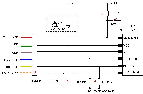
Microchip does not recommend any specific circuit for In-Circuit Serial Programming (ICSP). Various diagrams exist for different tools, such as Pro Mate and PICKit2, which feature similar circuitry with minor variations. Some schematics may suggest resistor values that are...