
BEAM pummer circuits
The PowerSaver Flasher circuit is designed to optimize energy efficiency while providing visually appealing light effects. The core of the circuit utilizes a 74HC14 hex inverter, which is known for its fast switching capabilities and low power consumption. This IC is configured in an astable multivibrator mode to generate a square wave output, which drives the LED(s) connected to it.
The capacitive output coupling method employed in this design allows for the generation of brief, intense flashes of light, which are visually striking and help to conserve energy. The use of a 1F capacitor charged to 5.5V provides ample energy storage for the LEDs, allowing them to operate for extended periods. The capacitor discharges through the LEDs, producing bright flashes while maintaining a low average current drain.
For each LED circuit, it is recommended to connect two LEDs in parallel or series, depending on the desired brightness and voltage requirements. The circuit can support up to 12 LEDs when configured properly, making it versatile for various applications such as decorative lighting or signaling.
The timing of the flashes can be adjusted by selecting different resistor values for the timing network connected to the 74HC14. A range of resistors from 1MΩ to 4.7MΩ can be used to create variations in the flashing frequency, which enhances the random light show effect. This variability allows for customization of the display to suit specific aesthetic preferences or requirements.
In summary, the PowerSaver Flasher is a highly efficient LED driver circuit that utilizes capacitive coupling and a 74HC14 inverter to create dynamic lighting effects while minimizing energy consumption. The careful selection of components and configuration enables a wide range of applications, making it suitable for both decorative and functional lighting solutions.The PowerSaver Flasher uses capacitive output coupling to produce brighter shorter flashes and has a much lower average current drain than standard bicore or 74HC14 flashers. The PS Flasher with one LED circuit (2 LEDs) runs all night from a 1F capacitor charged to 5.5V. Up to 12 LEDs can be controlled with one 74HC14 flasher and probably would run for 2 hours from a full charge.
Use a range of timing resistors between 1M and 4.7M for each oscillator to give a random light show appearance. 🔗 External reference
Related Circuits
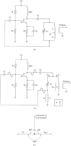
A widely recognized circuit is the Hartley oscillator, which is characterized by a tapped coil within the LC tank circuit. The tap point of the coil is grounded. The oscillator's amplifier section functions as a common-emitter amplifier, resulting in...
This document provides a guide on understanding a simple computer system and its operation. It will examine the BASIC programming language and its statements, enabling communication with external circuitry. The document will also explore how to interface electronic circuits...
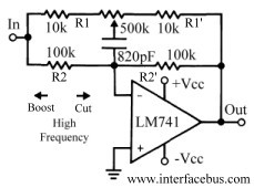
This discussion continues from the audio tone control topic, which introduced both passive and active tone controls. The follow-up topics may include a 2-Band Active Tone Control or a 3-Band Active Tone Control. An audio equalizer is utilized to...
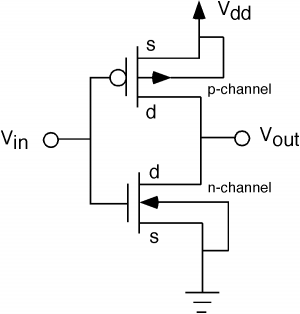
The fundamental issue presented is the perception that logic gates in a circuit seem to generate power from nothing, which contradicts the principles of physics. For instance, consider two NOT gates connected in series. It appears that the first...
The 15 kHz frequency is used to drive the flyback transformer; however, the high voltage at the output is DC. The flyback transformer operates by converting low-voltage DC into high-voltage DC, utilizing a specific driving frequency, in this case, 15...
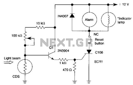
When the light beam that falls on the CDS photocell is interrupted, the transistor (EN3904) conducts, triggering SCR1 (CI06) and activating the alarm bell. SI resets the SCR. The alarm bell should be a self-interrupting electromechanical type. The lamp...
Warning: include(partials/cookie-banner.php): Failed to open stream: Permission denied in /var/www/html/nextgr/view-circuit.php on line 713
Warning: include(): Failed opening 'partials/cookie-banner.php' for inclusion (include_path='.:/usr/share/php') in /var/www/html/nextgr/view-circuit.php on line 713