
Single Cell 1.5V Hearing Aid
The hearing aid circuit operates by amplifying low-level audio signals to make them audible for individuals with hearing impairments. The primary components typically include a microphone, an amplifier, and a speaker (earpiece).
The microphone captures ambient sounds, converting them into electrical signals. These signals are often very weak, necessitating amplification for proper hearing. The amplifier, which can be implemented using operational amplifiers (op-amps) or dedicated audio amplifier ICs, increases the signal strength. The gain of the amplifier must be carefully selected to ensure that it enhances the sound without introducing excessive noise or distortion.
The output of the amplifier is then fed to an 8-ohm earpiece, which converts the amplified electrical signals back into sound waves. The earpiece is designed to match the output impedance of the amplifier, ensuring efficient power transfer and optimal sound quality.
Power management is crucial in hearing aid circuits, especially since they are often battery-operated. The 1.5V supply is typically derived from standard batteries, such as AA or AAA cells. Circuit design considerations may include low-power components and techniques to extend battery life, such as automatic shut-off features when not in use.
Additional features may include volume control, tone adjustment, and noise filtering to enhance the listening experience. These can be achieved through the use of potentiometers and passive components, or more advanced digital signal processing techniques in modern designs.
Overall, the hearing aid circuit is a compact and efficient system tailored to improve sound detection and clarity for users with hearing difficulties.This is a hearing aid circuit with 1.5v supply. This circuit is used to detect very faint sounds, then deliver the sounds to an 8 ohm earpiece. This circuit. 🔗 External reference
Related Circuits
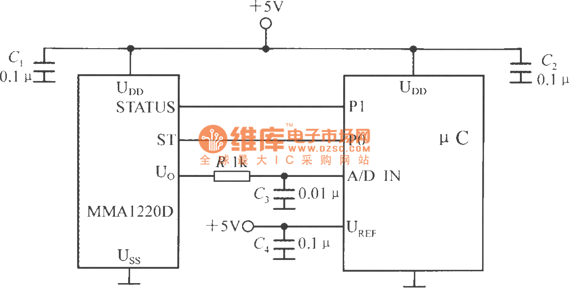
The microcontroller within the A/D converter can utilize a PIC MCU produced by Microchip. The MMA1220D's state and self-test pins are connected to the P1 and P0 ports of the microcontroller, with its output voltage sent to the input...
The cell phone shield circuit employs two NE555 timer integrated circuits (ICs): one configured as a simple astable multivibrator (IC2) and the second as a monostable multivibrator (IC3). The astable multivibrator utilizes timing resistors R1 and R2 but does...
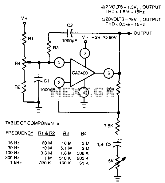
The adjustment of R4 contributes to the comparatively symmetrical output transfer characteristic of the CA3420 BiMOS operational amplifier. To extend the lower operating frequency, remove C3 and use a dual supply. The CA3420 is a high-performance BiMOS operational amplifier that...
A DIY GSM jammer schematic diagram designed specifically for GSM1900 frequencies ranging from 1930 MHz to 1990 MHz. The GSM1900 mobile phone network is utilized in the USA, Canada, and most South American countries. This cell phone jammer is...
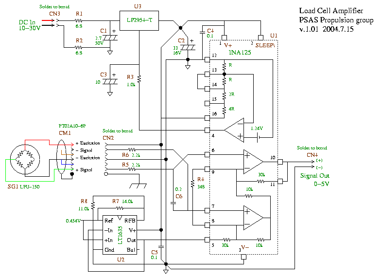
A schematic for a load cell amplifier has been discovered. Load cell amplifiers are typically expensive, with prices ranging from 100 to 300 USD. However, it is possible to build a personal load cell amplifier at a lower cost....
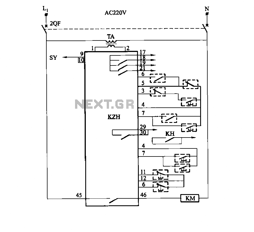
It utilizes the SHD series of electronic control equipment modules. The fan control box KZH functions as the HKD 1F electronic module. The SHD series of electronic control equipment is designed for various applications, including fan control systems. Within this...