
The interface circuit between single-chip accelerometer MMA1220D and microcontroller
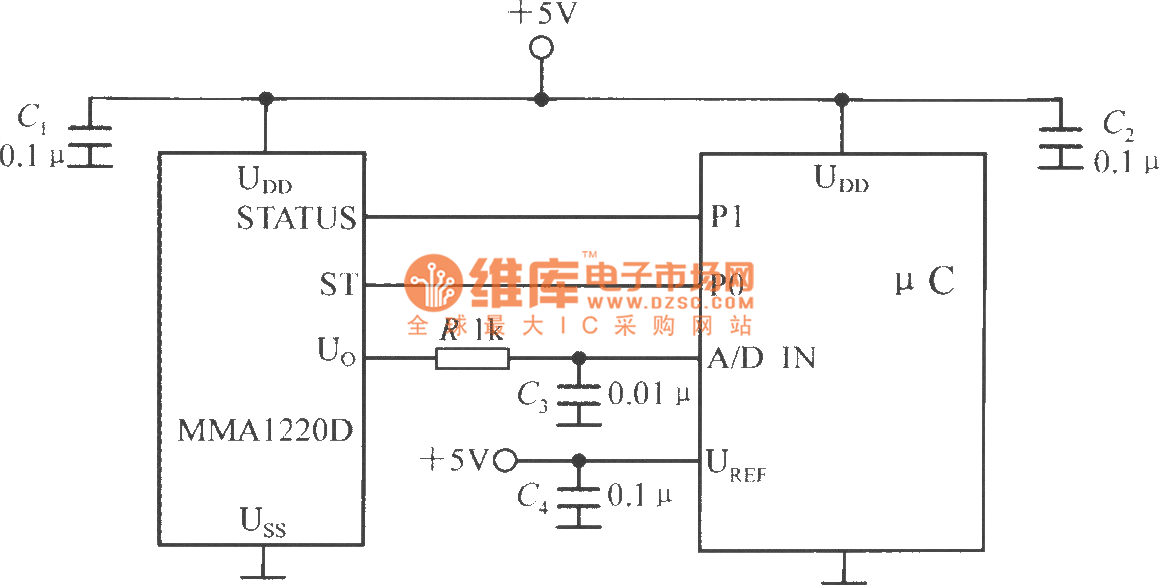
The circuit involves a microcontroller unit (MCU) from Microchip, specifically a PIC MCU, which interfaces with an A/D converter. The MMA1220D sensor provides data regarding its state and self-test operations through its designated pins, which are connected to the microcontroller's P1 and P0 ports. This configuration allows the microcontroller to monitor the sensor's performance and ensure accurate readings.
The output voltage from the MMA1220D is directed to the input of the A/D converter, facilitating the conversion of the analog signal into a digital format that the microcontroller can process. The A/D converter is a critical component that translates the varying voltage levels from the sensor into quantifiable digital values.
Decoupling capacitors, C1 and C2, are employed to stabilize the power supply by filtering out noise and ensuring a clean voltage supply to the A/D converter and the microcontroller. This is essential for maintaining the integrity of the signal being processed.
The reference voltage (UREF) for the A/D converter is a vital parameter that defines the voltage range for the conversion process. Proper connection of the UREF pin is crucial as it sets the maximum input voltage level that the A/D converter can accurately measure. The overall design ensures that the microcontroller can effectively communicate with the A/D converter and the MMA1220D sensor, resulting in reliable data acquisition and processing for various applications.The microcontroller within A / D converter can use PIC MCU within A / D converter produced by the Microchip. MMA1220D`s state end and self-test end are connected to the P1, P0 ports of ?C, its output voltage is sent to the A / D converter input end.
C1, C2 are the power supply decoupling capacitors. A / D converter`s reference voltage side ( UREF ) is conne.. 🔗 External reference
Related Circuits
The circuit was designed to create a line preamplifier using double triode tubes. It consists of three parts, including the main preamplifier. The line preamplifier circuit utilizing double triode tubes is structured to enhance audio signals by amplifying low-level signals...
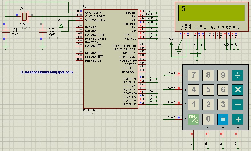
This PIC microcontroller tutorial provides a straightforward method to interface any keypad (e.g., 4x4 or 4x3) with the PIC16F877 microcontroller. This code is written... The tutorial outlines the steps necessary to connect a keypad to the PIC16F877 microcontroller, which is...
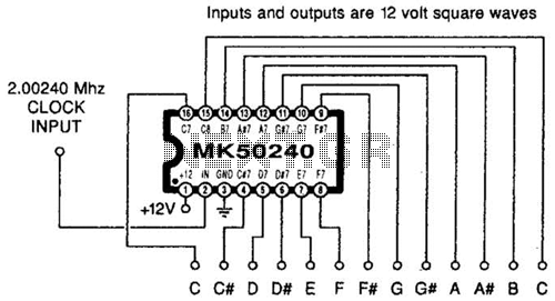
Using an MK50240, this circuit generates 12 top octave tones. The input and output lines can be separated using a binary divider IC to achieve the lower notes. Inputs and outputs are 12-volt square waves. The MK50240 is a specialized...

This circuit is designed to automatically adjust the brightness of lights based on the ambient light intensity. In bright conditions, the lights remain off, while in low ambient brightness, the lights are activated. The circuit incorporates a thyristor (VT1)...

The design of an FM radio transmission frequency band enables compatibility with any FM radio receiver, allowing the high-frequency signal to be transmitted and restored from an audio signal. This technology serves various applications. Applications of a wireless microphone...
This circuit provides a straightforward and efficient method for interfacing two relays in switching applications. The relay driver utilizes a standard BC547 NPN transistor (or equivalent) to enhance the input impedance. It is a widely used driver capable of...