
Load Cell Amp Schematic
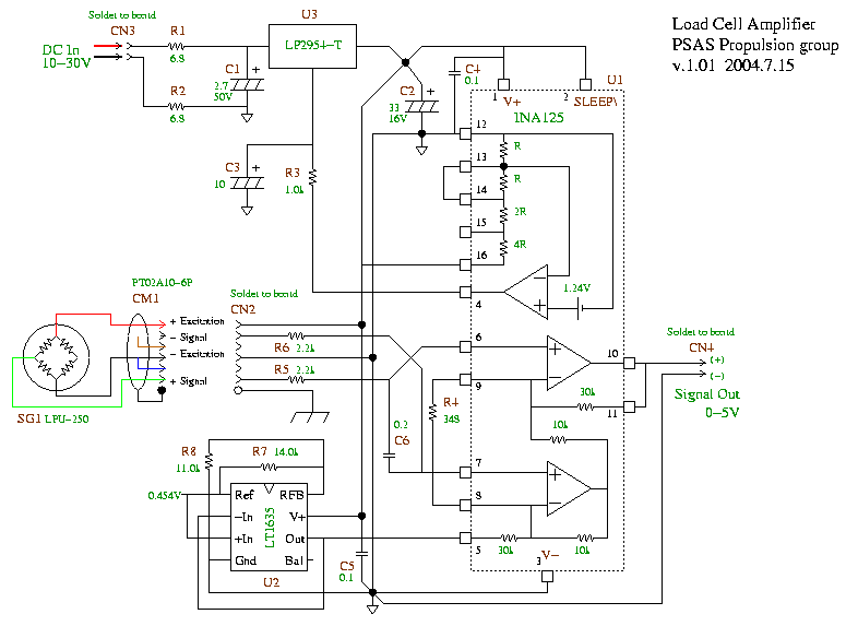
The load cell amplifier circuit is designed to amplify the small signal generated by the load cell, which is a type of transducer that converts force or weight into an electrical signal. The use of the AMP04 or INA125 amplifiers allows for precision and stability in the output signal. The circuit typically includes a power supply, input terminals for the load cell, and output terminals for the amplified signal.
In the lead-acid battery charger circuit, the initial voltage of 2.5 V per cell is critical for fast charging. The design ensures that as the battery approaches its full charge, the current diminishes, preventing overcharging and extending the battery's lifespan. The use of a solar panel for power generation is an eco-friendly solution, and the inclusion of a diode protects the circuit from reverse current flow.
The battery charger schematic for the 6V gel cell type involves careful selection of resistors and capacitors to ensure proper charging characteristics. The specified resistors, such as R4, R5, R6, and R7, are precision components that help maintain the desired charging current and voltage levels. The use of ceramic capacitors (C1 and C2) aids in stabilizing the circuit and filtering out noise.
For the multi-cell lithium battery charger, the constant current of 60 mA is a critical parameter, as it ensures safe charging rates for AA cells while the cutoff voltage of 2.4V prevents damage to the cells. The design accommodates 2 to 6 cells in series, allowing for flexibility in battery pack configurations.
The overall circuit design emphasizes efficiency and safety, with the output power specifications ensuring compatibility with various speaker loads. The requirement for a supply voltage of 8 to 24V DC ensures that the circuit can operate effectively across a range of applications, making it versatile for different electronic projects. The emphasis on achieving maximum output power with a higher voltage supply indicates a design consideration for performance optimization in audio applications.I`ve found some interesting schematic of Load Cell amplifier. As we know, load cell amplifier is pretty expensive with fair price range of 100-300 USD. You may built your own load cell amplifier to get the lower cost. Load Cell Amplifier using AMP04: source: Load Cell Amplifier using INA125: source: source: The following diagram is the circuit diagram of Lead-Acid battery charger. This circuit provides an initial voltage of 2. 5 V per cell at 25 ƒ to quickly charge the battery. The charging current decreases as the battery is charging, and when the current drops to 180 mA, the charging circuit reduces the output voltage of. Powered with solar panel, the circuit will give you 5V pure regulated DC voltage. The circuit is made up of an oscillator transistor as well as a regulator transistor. The solar panel charges the battery when sunlight is bright enough to generate a voltage above 1. 9v. A diode is necessary between the panel and also. The following diagram is the battery charger schematic for 6V Gel Cell battery type. Component Parts List: R1 = 22 ohm, 1W R2 = 270 ohm R3 = 220 ohm *R4 = 715 ohm, 1% *R5 = 3. 57K, 1% *R6 = 1. 40K, 1% *R7 = 1. 47K, 1% C1 = 0. 1 F, ceramic C2 = 0. 1 F, ceramic. This battery charger circuit is used for rechargable lithium battery. Charging is accomplished with a constant current of 60 mA for AA cells to a cutoff of 2. 4V per cell, at which point the charge must be terminated. The charging system shown is designed for multi-cell battery pack of 2 to 6 series connected cell. This circuit power output will be 10 watt on each channel with 4 ohm speaker resistance. The supply voltage required for this circuit is 8 - 24V DC at 1 to 2 Amps. Maximum output power will only be obtained with a power supply of at least 20V and greater than 1. 5 A, and using. 🔗 External reference
Related Circuits
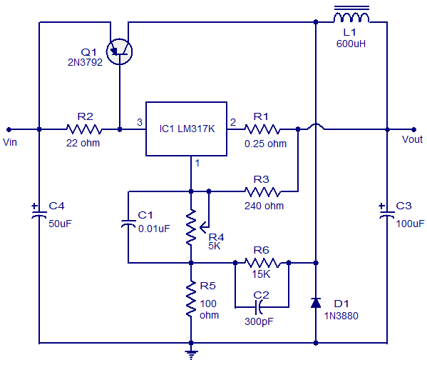
This circuit illustrates a 3A Switching Regulator Circuit based on the LM317K integrated circuit. It is designed to be simple and cost-effective. The 3A Switching Regulator Circuit utilizing the LM317K IC serves as a versatile voltage regulation solution, capable of...

For high-impedance (7,500 ohms) applications, this amplifier will provide a voltage gain of approximately -gm/ZL, where ZL is the load impedance in ohms and gm is approximately 12 x 10^-3 for the 40673 FET. The G2 voltage can be...
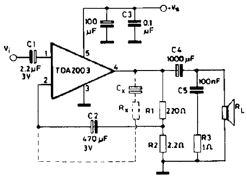
The TDA2003 offers enhanced performance while retaining the same pin configuration as the TDA2002. It maintains the advantageous features of the TDA2002, including a minimal number of external components, ease of assembly, and savings in both space and cost....
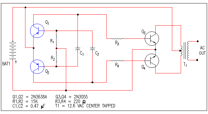
A small bias on the bases of Q1 and Q2 through R1 and R2 assists in initiating the circuit. This provides each transistor's base with a slight forward bias, enabling both transistors to conduct when the circuit is initially...
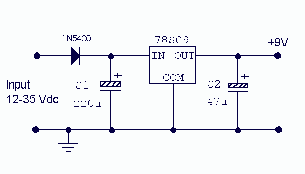
There is little to be said about this circuit. All the work is done by the regulator. The 78S09 can deliver up to 2 amps continuous output whilst maintaining a low noise and very well regulated supply. The circuit...
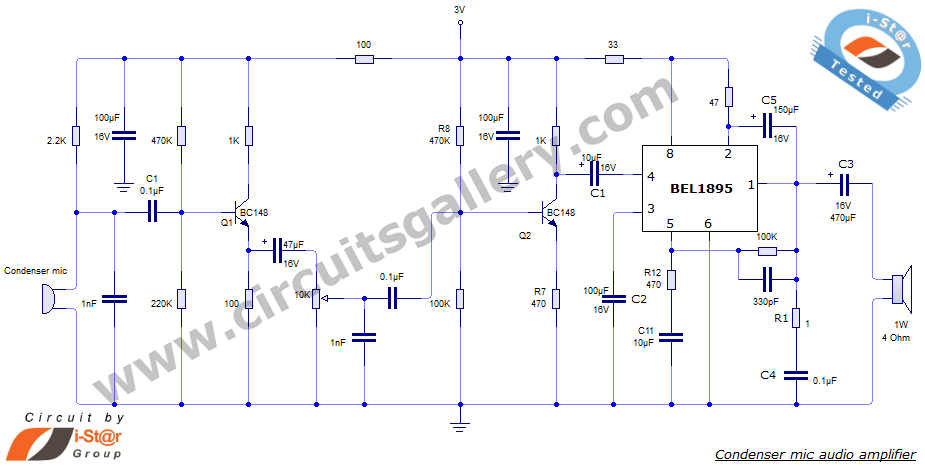
This document presents an audio amplifier circuit suitable for use in walkie-talkies, low-power transmitters, and packet radio receivers. The circuit utilizes a condenser microphone audio amplifier that delivers high-quality audio output of 0.5 watts at 3 volts. The design...