
Single Op-Amp 3 Band Equalizer circuit
The 3 Band Equalizer circuit serves to enhance audio signals by allowing users to adjust specific frequency ranges according to their preferences. The design typically comprises three adjustable filters, each dedicated to one of the frequency bands: treble, midrange, and bass.
The operational amplifier is configured in a feedback loop, enabling it to amplify and modify the audio signal. Each band is controlled by a potentiometer, which adjusts the gain of the op-amp for that specific frequency range. The treble control affects the higher frequencies (typically above 3 kHz), the midrange control adjusts frequencies around 1 kHz to 3 kHz, and the bass control influences lower frequencies (below 1 kHz).
The circuit may include passive components such as resistors and capacitors to define the cutoff frequencies of the filters. By tuning these components, the desired frequency response can be achieved. The output of the op-amp can be connected to a speaker or further audio processing stages, allowing for a customized listening experience.
In practical applications, the 3 Band Equalizer circuit can be integrated into audio devices such as mixers, amplifiers, or standalone equalizers, enhancing sound quality and providing users with the ability to tailor audio output to their liking. Proper layout and grounding techniques should be employed to minimize noise and ensure optimal performance of the circuit.This is a 3 Band Equalizer circuit. This circuit is made to control the treble, middle and bass range. This circuit uses a single op-amp. With single op-amp we. 🔗 External reference
Related Circuits
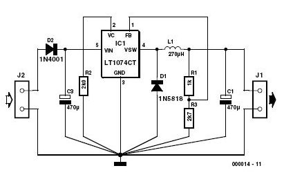
This 3-volt car adapter circuit is based on a standard LT1074CT switching regulator IC. The schematic shows the LT1074CT used as a positive step-down regulator. The 3-volt car adapter circuit employs the LT1074CT, which is a high-efficiency switching regulator capable...
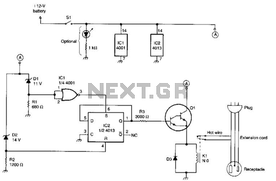
This circuit utilizes a pair of Zener diodes to monitor the voltage of a 12-V battery. When the voltage drops below 11 V, diode D1 ceases to conduct, causing pin 3 of flip-flop IC2 to go high. This action...
This circuit functions with inaudible (ultrasonic) sound. Sound of frequency up to 20 kHz is audible to human beings. The sound of frequency above 20 kHz is called ultrasonic sound. The circuit described generates (transmits) ultrasonic sound of frequency...
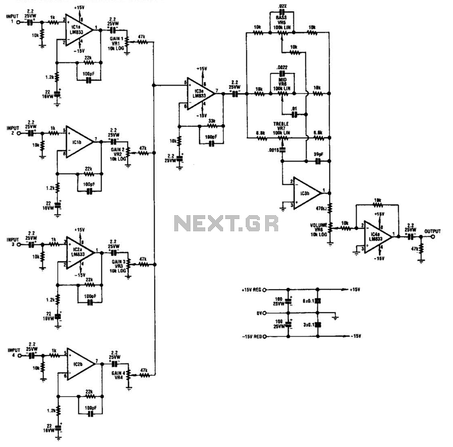
IC1-a, IC1-b, IC2-a, and IC2-b all operate with a gain of approximately 19. Their outputs are combined through level-control potentiometers, and the resulting signal is amplified by IC3-a before being sent to the tone-control stage IC3-b. Finally, the output...
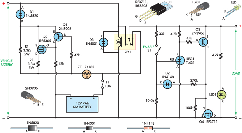
The SLA battery is charged from the vehicle's battery. When the engine is running, the voltage remains fairly constant, which greatly simplifies the charging circuit. If the SLA battery is fully charged, any further charging current from the vehicle...
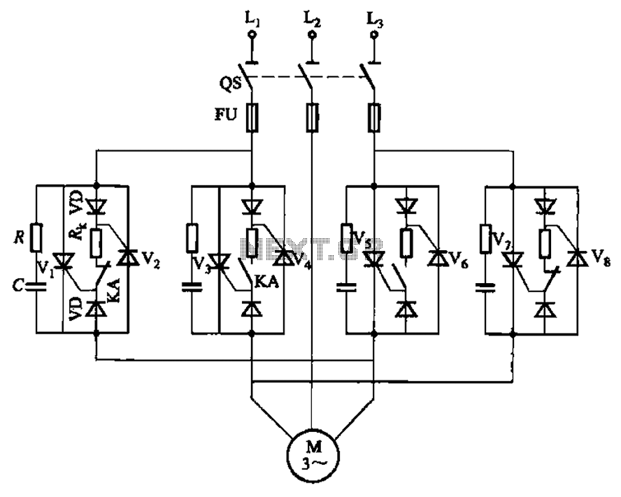
The circuit depicted in Figure 3-69 is designed for applications requiring frequent timing control for motor reversing operations. In this configuration, thyristors V1, V2, V7, and V5 are utilized for positive control of rotation, while thyristors V3, V4, and...