
Battery Watchdog Circuit

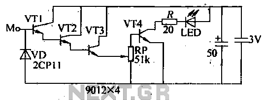
The circuit operates as a battery voltage monitoring and charging control system. The Zener diodes are selected based on their breakdown voltages, with one Zener diode (D1) set to trigger at a lower threshold of 11 V and the other (D2) at an upper threshold of 14 V. This creates a hysteresis effect that prevents rapid cycling of the charger on and off, ensuring stable operation.
When the battery voltage falls below 11 V, D1 becomes reverse-biased, which results in pin 3 of flip-flop IC2 transitioning to a high state. This transition activates the output of the flip-flop, which then drives the base of transistor Q1. Q1, when turned on, allows current to flow through K1, which represents the battery charger relay or control circuit. This connection initiates the charging process, thereby restoring the battery voltage.
On the other hand, when the battery reaches a voltage above 14 V, D2 becomes forward-biased. This condition causes the reset pin of flip-flop IC2 to be activated, which in turn resets the flip-flop and deactivates Q1. The deactivation of Q1 interrupts the current flow to K1, effectively disconnecting the battery charger from the circuit. This dual Zener diode configuration provides a reliable and efficient method for maintaining the battery within a safe operating voltage range, preventing overcharging and deep discharging, which can significantly extend the life of the battery.
Overall, this circuit design exemplifies a simple yet effective approach to battery management, utilizing common electronic components to achieve critical functionality in battery-operated systems. This circuit uses a pair of Zener diodes to monitor battery voltage of a 12-V battery. If below 11 V, 1)1 ceases to conduct, pin 3 of 102 goes high, setting FF IC2 turning on Ql, Kl, and the battery charger. At excess of 14-V battery voltage (full charge), D2 conducts, resetting FF IC2, and cutting off the battery charger. 🔗 External reference
Related Circuits
In 2011, designing a frequency converter circuit typically involves selecting an integrated circuit (IC) that meets specific requirements regarding gain and mixer spurious products, along with adding a couple of filters and a power supply. Often, the oscillator is...
The internal disconnection circuit for a blanket operates on the principle of induction. It includes a wire approximately 2 cm in length that senses the proximity of a charged mains power source. When the sensing wire is close to...
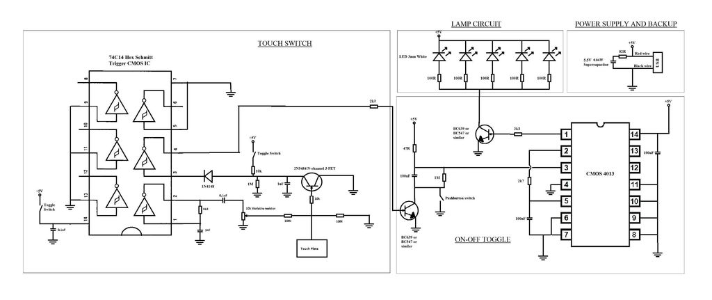
A touch switch for a USB-powered desk lamp is malfunctioning. The circuit diagram, layout, and pictures are provided below. The design incorporates circuits sourced from two websites, specifically the fourth circuit. The output of the touch switch is connected...
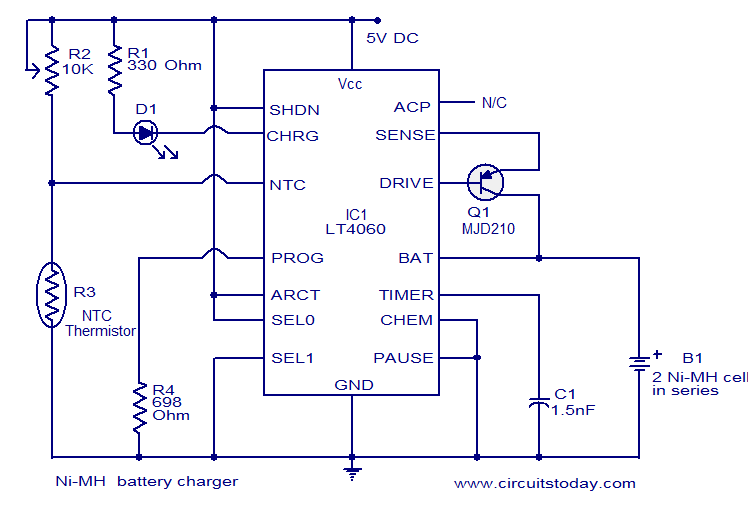
This circuit diagram represents a highly efficient Ni-MH battery charger utilizing the LT4060 integrated circuit from Linear Technologies. The circuit can also accommodate Ni-Cd batteries with minor modifications. To charge Ni-Cd batteries, the CHEM pin (pin 12) of the...
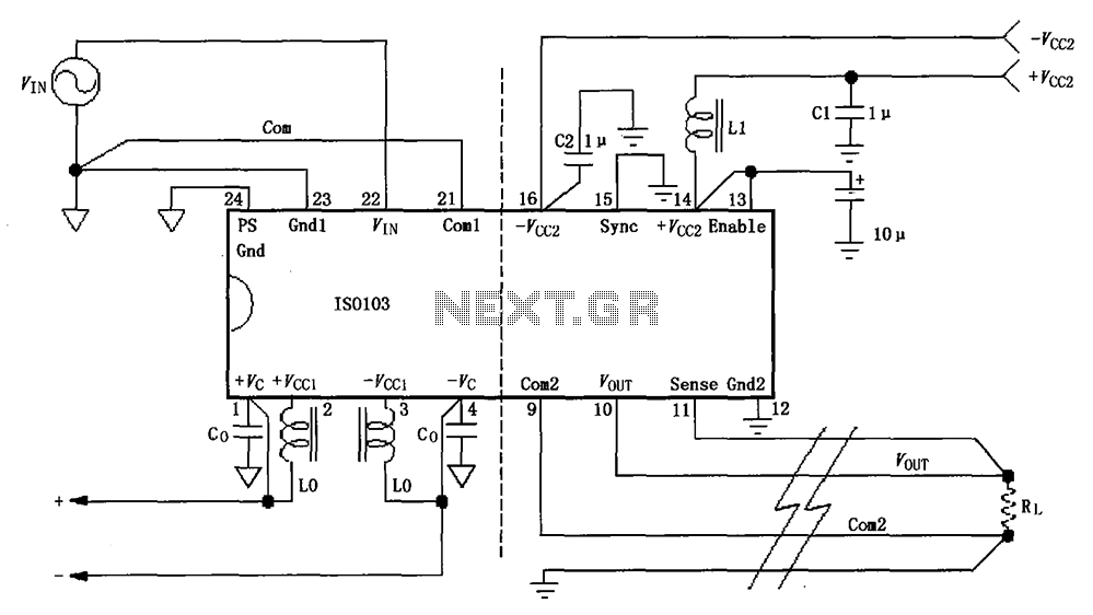
The basic connection circuit for the ISO103 signal and power supply is illustrated. Each power supply terminal must include a bypass filter. If the isolated power supply output current exceeds 15mA, it is advisable to utilize an external filter...

This is a design circuit for a soft light dimmer. The circuit utilizes the IGBT STGP10N50A and the TS555 timer as the main components. The timer is triggered by the zero crossing voltage pulse. The time constant, determined by...