
Single Transistor Audio Mixer Circuit
This audio mixer circuit employs a single transistor to facilitate the mixing of audio signals. The transistor operates in a common emitter configuration, where the input audio signals are fed to the base terminal. The base current controls the transistor's operation, allowing it to amplify the audio signals effectively.
The use of a base-driven transistor enables the circuit to achieve a high input impedance, making it suitable for interfacing with various audio sources without significantly loading them. The emitter current control mechanism allows for better stability and linearity in the amplification process, ensuring minimal distortion of the audio signals.
In this design, resistors are typically used to set the biasing conditions for the transistor, ensuring that it operates in the active region. Coupling capacitors may be included at the input and output stages to block any DC components, allowing only the AC audio signals to pass through. This is crucial for maintaining the integrity of the audio signals being mixed.
The output of the mixer can be connected to subsequent stages in an audio amplification system, such as additional amplifiers or equalizers. The simplicity of this single transistor audio mixer makes it an ideal choice for basic audio mixing applications, providing an efficient and effective solution for combining multiple audio sources into a single output signal.This single transistor audio mixer is used in an amplifier circuit design with base driven transistor and with its emitter being current controlled, most o.. 🔗 External reference
Related Circuits
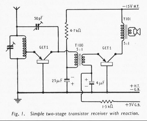
The world's first practical crystal amplifying device was introduced in 1948, marking the beginning of commercially available transistor radios in Britain. At that time, an average radio enthusiast or constructor would have been adjusting to new miniature glass valves,...

The Mini AV Test Box circuit is designed with simplicity and efficiency in mind. It consists of three main sections, which are clearly delineated in the schematic. The primary components utilized in this circuit include the 7805 voltage regulator,...
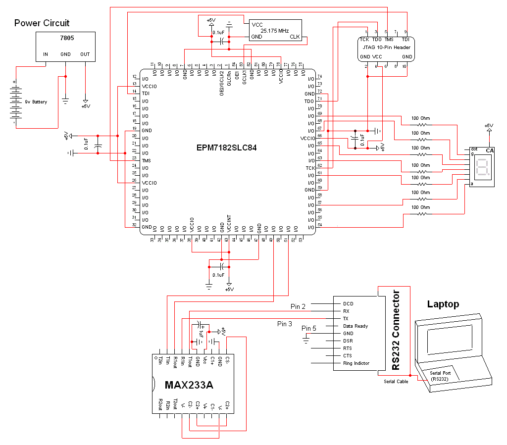
The schematic for this project is a modified version of the CPLD development board schematic. Several new components have been added for this project, and the completed schematic can be viewed below. The main components in the schematic are...
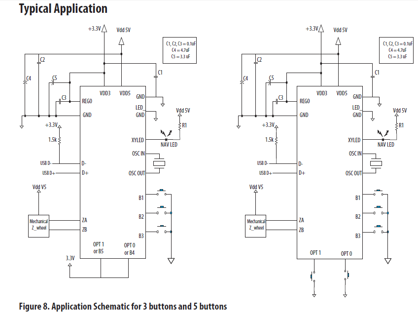
The chip in the center with small bullet holes is likely proprietary. It is possible to salvage a few components from it, although understanding the circuit is not necessary for this purpose. Additionally, it is confirmed that the device...
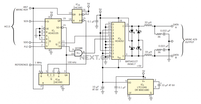
The physical transmission medium for the 429 standard is 78Ω shielded, twisted-pair cable that uses a complementary, differential bipolar RZ (return-to-zero) waveform. The voltages are the net differentials that the biphase drive develops: For example, the differential is 10V...
This project involves a ding-dong doorbell circuit utilizing the 555 Integrated Circuit (IC). In a previous article, a simple doorbell circuit using the UM66 IC, a CMOS three-terminal melody IC, was discussed. The current circuit employs the NE555 IC...
Warning: include(partials/cookie-banner.php): Failed to open stream: Permission denied in /var/www/html/nextgr/view-circuit.php on line 713
Warning: include(): Failed opening 'partials/cookie-banner.php' for inclusion (include_path='.:/usr/share/php') in /var/www/html/nextgr/view-circuit.php on line 713