
Single Transistor Relay Toggle Circuit
The described circuit utilizes a double pole, double throw (DPDT) relay in combination with a single transistor to facilitate the toggling of the relay through a momentary push button. The design incorporates two sets of contacts within the relay: one set is dedicated to controlling the load, while the second set provides feedback to maintain the relay's state, either activated or deactivated.
When the momentary push button is pressed, a small current flows through the transistor, which in turn energizes the relay coil. This action switches the relay contacts, allowing the load to be powered. The feedback mechanism is achieved through the second set of contacts, which can be used to create a self-latching circuit. This means that once the relay is activated, it will remain in that state even after the push button is released, until it is toggled again by pressing the button.
The circuit design also allows for multiple push buttons to be connected in parallel. This feature enables control of the relay from various locations, providing flexibility in operation. Each push button, when pressed, will send a signal to the transistor to toggle the relay, ensuring that the load can be controlled conveniently from different points.
In terms of component selection, the relay should be rated appropriately for the load it will control, and the transistor must be capable of handling the current required to energize the relay coil. Additionally, resistors may be needed to limit the current to the transistor and protect the circuit from potential damage. Proper circuit layout and grounding practices should be followed to ensure reliable operation and minimize interference.The circuit requires a double pole, double throw relay in conjunction with a single transistor to allow toggling the relay with a momentary push button. One set of relay contacts is used to control the load, while the other is used to provide feedback to keep the relay activated or deactivated.
Several push buttons can be wired in parallel to allow toggling the relay from different locations.. 🔗 External reference
Related Circuits
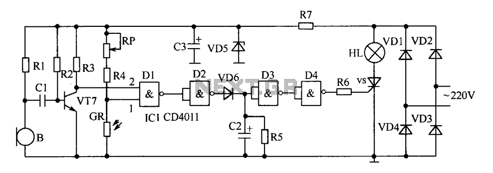
The delay-saving lamp circuit functions as a sound and light control delay energy-saving lighting system. It can directly replace a standard light switch without modifying the existing lighting circuits. In bright or daytime conditions, the sound control feature ensures...
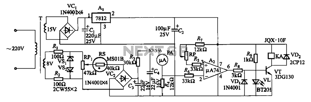
The humidity alarm system is based on integrated circuits and relays, utilizing the pA741 circuit. The MS01 employs a wet-type humidity resistance element as a probe. When the humidity exceeds a predetermined value, specifically set at 6 feet high,...

This simple tone control (bass and treble control) can be utilized in various audio applications. It can be integrated into amplifiers, function as a standalone control module, or even be incorporated into new and innovative instruments. The circuit employs...
Remove the 6 mm screw that secures the lower rear fairing cover. This cover is the black plastic piece to which the spark plug protectors are attached. Only the machine screw should be removed; do not detach the lower...
The circuit is straightforward yet capable of outstanding performance. It has been specifically designed as an amplifier for the digital sound card in a computer. Audio input can be sourced from any two-channel line-level device such as a television,...
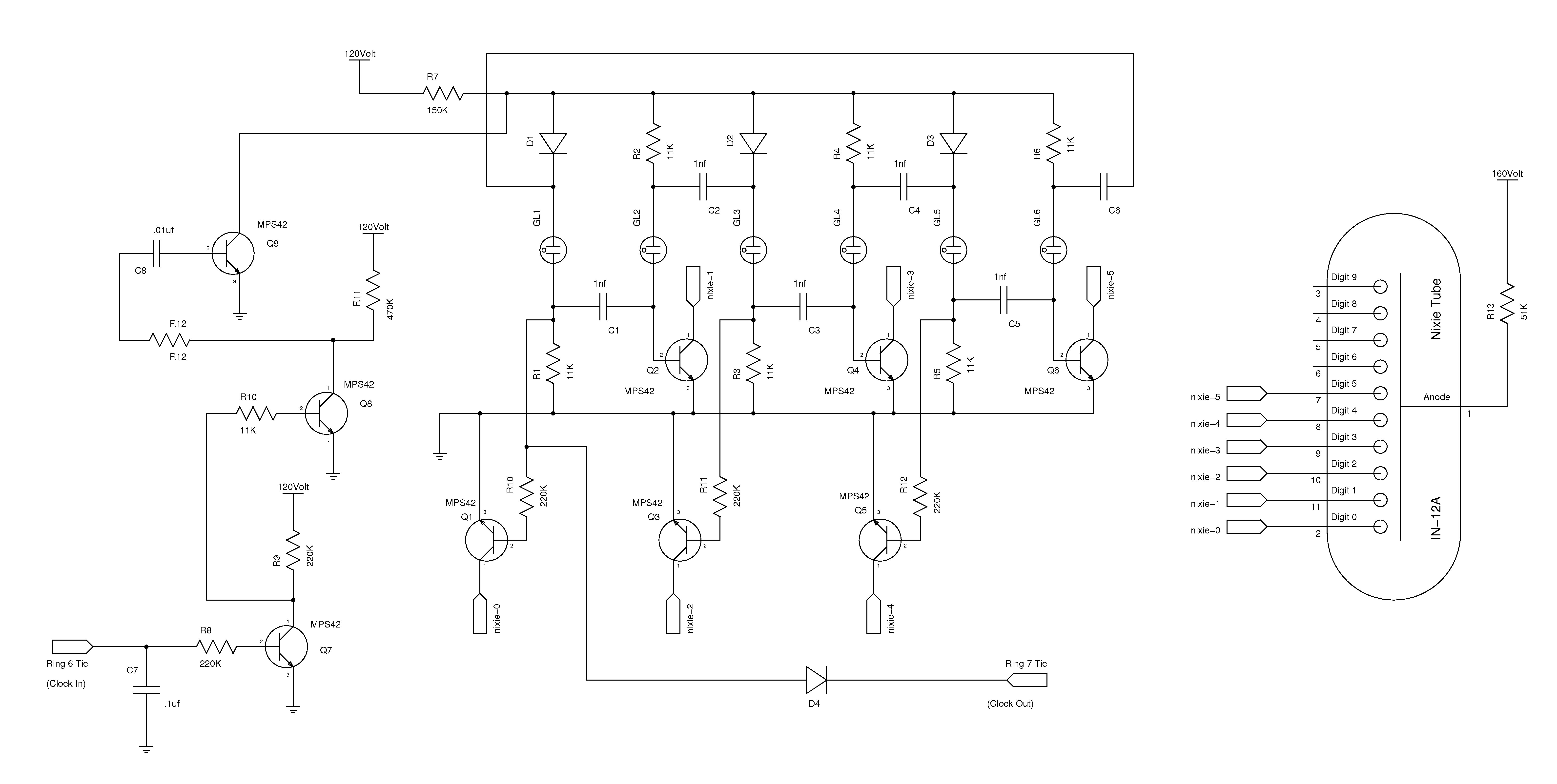
The nixie tube clock consists of a high-voltage power supply, seven ring counters, and an Atmel AVR processor. The power supply is shown in Schematic 1. It takes 12 volts AC and converts it to DC, which drives the...