
Air humidity measuring circuit 2
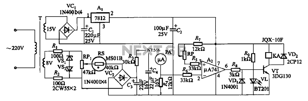
The humidity alarm system is designed to monitor and respond to humidity levels in various environments. The core of the system is the pA741 operational amplifier, which provides the necessary signal conditioning for the humidity sensor. The MS01 humidity sensor, which operates on the principle of resistance change with moisture absorption, serves as the primary detection element.
When the humidity level rises above the defined threshold, the resistance of the sensor decreases, resulting in a voltage change at the input of the pA741. This change is amplified and processed to drive relay KA. The relay, upon activation, completes the circuit for the alarm, alerting users to the high humidity condition.
To fine-tune the system, the adjustment potentiometer RP is incorporated into the circuit. This component allows the user to set the desired humidity threshold, providing flexibility for different applications and environments. The potentiometer is connected to a voltage divider configuration, which adjusts the reference voltage fed to the pA741, thereby determining the activation point for the relay.
The entire circuit can be powered by a standard DC power supply, and it is essential to ensure that all components are rated for the operational voltages and currents to avoid damage. Proper layout and grounding practices should be followed in the schematic design to minimize noise and ensure reliable operation of the humidity alarm system. Based integrated circuits and relays KA constitute humidity alarm value it uses pA741 circuit. MS01 using a wet-type humidity resistance element as a probe. When the humidity e xceeds a predetermined value, Az 6 feet high, relay KA pull, turn the alarm circuit. Adjustment potentiometer RP, may decide the upper limit of humidity.
Related Circuits
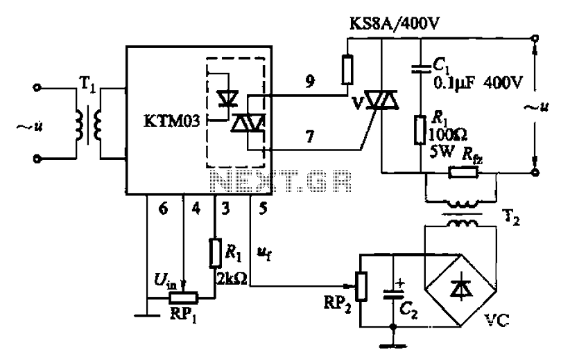
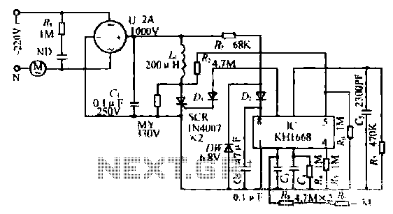
An adjustment potentiometer (RP) is utilized to set the voltage across the load resistor (Rfz) to a predetermined value. The real-time closed-loop control is achieved through the potentiometer (RPz). Open-loop control is functional as long as the feedback voltage...
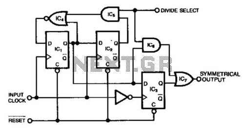
This circuit generates a symmetrical waveform by dividing the input frequency by either 2 or 3. The Divide Select input governs the division factor. When the Divide Select input is high, flip-flops IC1 and IC2, along with the associated...
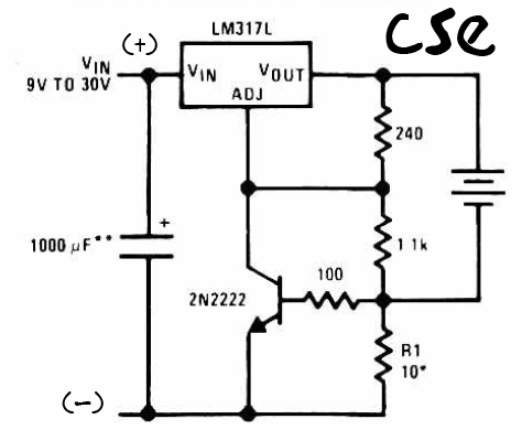
This is a straightforward charger designed for 9V to 30V batteries, primarily operated by the IC LM317L and a 2N222 transistor. It utilizes direct input DC voltage, and a recommended capacitor of 1000µF is included for filtering the output...
This project involves a simple doorbell circuit featuring the UM66 melody integrated circuit (IC), which is well-known for its melody generation capabilities. The IC is housed in a TO-92 transistor package and consists of only three pins, functioning as...
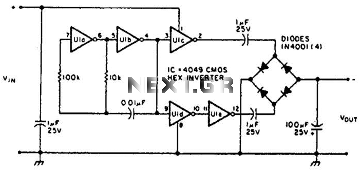
This circuit will provide a negative DC voltage that is approximately equal to the positive input voltage at no load and about 3 V less at a 10 mA load. The input voltage range is from +5 to +15...
The synchronous vibration circuit operates with a control logic that includes three primary components. An internal oscillator is initiated by a synchronization pulse, transitioning to a low state immediately after the pulse. Upon power activation, the internal circuitry undergoes...
Warning: include(partials/cookie-banner.php): Failed to open stream: Permission denied in /var/www/html/nextgr/view-circuit.php on line 713
Warning: include(): Failed opening 'partials/cookie-banner.php' for inclusion (include_path='.:/usr/share/php') in /var/www/html/nextgr/view-circuit.php on line 713