
Small Arduino DMX controller
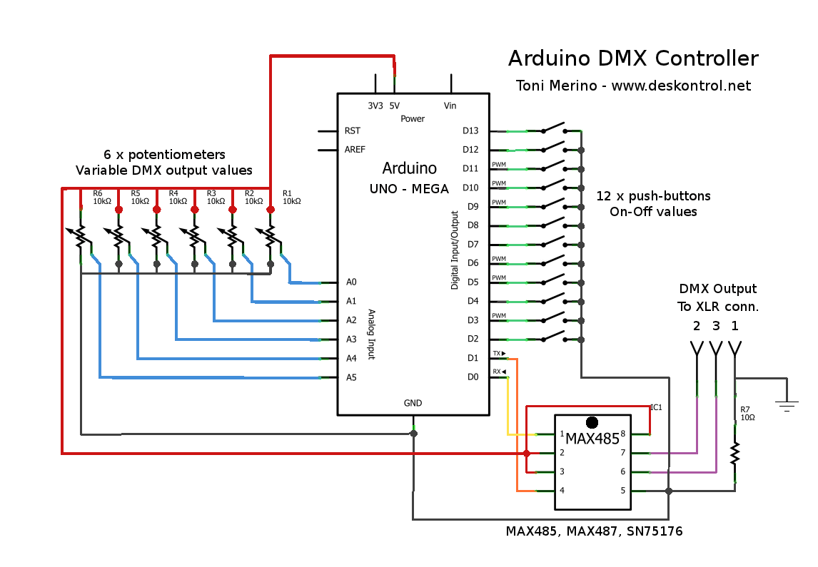
The Arduino DMX512 controller operates using a library that supports four DMX universes. The setup function configures the pins from 2 to 13 as inputs with pull-up resistors activated. This allows for the reading of button states and potentiometer values. The main loop continuously reads the analog values from the potentiometers, scales them to the appropriate range, and sends them to the corresponding DMX channels. The push buttons are also monitored, and their states are used to send either a maximum value (255) or zero to specific DMX channels based on whether the buttons are pressed or not.
The controller is designed to operate in standard DMX512 mode, allowing for efficient communication with compatible DMX devices.
The Arduino DMX512 controller is structured to facilitate interaction with various lighting and effect devices through DMX protocol. The design involves six analog channels, each connected to a potentiometer that allows for real-time adjustment of output values. The potentiometers are connected to the analog inputs of the Arduino, enabling the conversion of their readings from a 10-bit range (0-1023) to an 8-bit range (0-255) suitable for DMX transmission. The conversion is achieved through a scaling function that shifts the value right by two bits, effectively dividing it by four.
In addition to the analog inputs, the controller features twelve digital inputs linked to push buttons. These buttons are configured with internal pull-up resistors, ensuring that the input reads LOW (0) when pressed and HIGH (1) when not pressed. This configuration allows for straightforward monitoring of button states, which can be used to control additional DMX channels.
The setup function initializes the Arduino pins and configures the DMX transmission settings, including the starting address and the number of channels to transmit. The main loop continuously updates the DMX output based on the current readings from the potentiometers and the states of the push buttons. This loop ensures that the DMX channels reflect the real-time adjustments made by the user.
The overall design of the Arduino DMX512 controller is versatile and can be adapted for various applications, including theatrical lighting control, stage effects, and testing of DMX-compatible devices. The simplicity of the Arduino platform combined with the flexibility of the DMX protocol makes this controller an excellent choice for both hobbyists and professionals in the field of electronic control systems.How to make a small and useful Arduino DMX512 controller, which can use by example to handle a smoke machine with DMX, or as test equipment, etc In the configuration shown we have 6 channels with variable values, provided by 6 potentiometers connected to the Arduino analog inputs, 10-bit values are reduced to 8 bits (0-255 who are used by DMX), and 12 channels with on-off values with 12 push buttons connected to the digital inputs of the arduino, digital inputs are using the arduino internal pullup resistors, so if the button is pressed the input value is 0, and if it is free the input value is 1. // <7465> * #include
set_tx_address(1); // poner aqui la direccion de inicio de DMX // put here DMX start address ArduinoDmx0. set_tx_channels(100); // poner aqui el numero de canales a transmitir // put here the number of DMX channels to transmmit ArduinoDmx0.
init_tx(DMX512); // iniciar transmision universo 0, modo estandar DMX512 // starts universe 0 as TX, standard mode DMX512 } //end setup() void loop() { // seis entradas con potenciometros que envian valores DMX entre 0 y 255 a los canales 1 al 6 // six analog inputs with potentiometers, sending values from 0 to 255, to dmx output channels 1 to 6 ArduinoDmx0. TxBuffer[0] = scale(analogRead(0); // copiar valor de la entrada analogica 0 al canal DMX 1 // copy value from analog input 0 to DMX channel 1 ArduinoDmx0.
TxBuffer[1] = scale(analogRead(1); // copiar valor de la entrada analogica 1 al canal DMX 2 // copy value from analog input 1 to DMX channel 2 ArduinoDmx0. TxBuffer[2] = scale(analogRead(2); // copiar valor de la entrada analogica 2 al canal DMX 3 // copy value from analog input 2 to DMX channel 3 ArduinoDmx0.
TxBuffer[3] = scale(analogRead(3); // copiar valor de la entrada analogica 3 al canal DMX 4 // copy value from analog input 3 to DMX channel 4 ArduinoDmx0. TxBuffer[4] = scale(analogRead(4); // copiar valor de la entrada analogica 4 al canal DMX 5 // copy value from analog input 4 to DMX channel 5 ArduinoDmx0.
TxBuffer[5] = scale(analogRead(5); // copiar valor de la entrada analogica 5 al canal DMX 6 // copy value from analog input 5 to DMX channel 6 if (digitalRead(2) = LOW) // pulsador en pin 2 apretado // push-button on pin 2, is pressed ArduinoDmx0. TxBuffer[6] = 255; // enviar 255 al canal DMX 7 // send value 255 to DMX channel 7 else ArduinoDmx0. TxBuffer[6] = 0; // si no enviar 0 // push-button free, send 0 if (digitalRead(3) = LOW) // pulsador en pin 3 apretado ArduinoDmx0.
TxBuffer[7] = 255; // enviar 255 al canal DMX 8 else ArduinoDmx0. TxBuffer[7] = 0; // si no enviar 0 if (digitalRead(4) = LOW) // pulsador en pin 4 apretado ArduinoDmx0. TxBuffer[8] = 255; // enviar 255 al canal DMX 9 else ArduinoDmx0. TxBuffer[8] = 0; // si no enviar 0 // aG±adir aqui hasta el pin 13 // add here the others inputs } //end loop() uint8_t scale(uint16_t value) // scale values from 10 bits to 8 bits { if(value > 1023) // test for 10 bits limit value = 1023; return (value >> 2); // scale } //end scale() // <7465> * / <7465> * * * Title : Controlador DMX con Arduino * Version :
🔗 External reference
Related Circuits
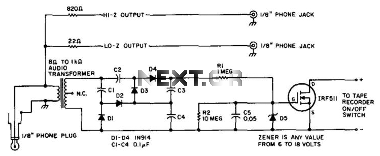
A tape recorder can be controlled by rectifying the audio input and driving an IRF511 power MOSFET to switch the tape recorder on when audio is present. This circuit was used with a communications receiver to record intermittent transmissions,...
The simplest form of motor controllers, apart from a basic on/off switch, is the contactor controller. This contactor controller is recommended for use in electric scooter projects. It is based on three 12V relays, two 12V batteries, two switches,...
Application note on designing linear and switch-mode (switching DC-DC converter current source) battery charger applications that require external microcontrollers and related system-level issues for notebook computers. The application note provides guidance on the design of both linear and switching DC-DC...
An HD44780 Character LCD is a liquid crystal display (LCD) device designed for interfacing with embedded systems. These screens are available in various configurations, including 8x1 (one row of eight characters), 16x2, and 20x4. The most commonly produced configuration...
The circuit for the solar-powered controller includes a switching circuit, a pulsing circuit, and a high-voltage output circuit. The external power components consist of a 1- to 5-W solar panel and a 12-V motorcycle or camcorder battery. The output...
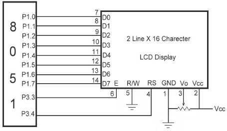
The link shows how to interface Alphanumeric LCD to 8051 Microcontroller. Liquid Crystal Display also called as LCD is very helpful in providing user interface as well as for debugging purpose. The most common type of LCD controller is...
Warning: include(partials/cookie-banner.php): Failed to open stream: Permission denied in /var/www/html/nextgr/view-circuit.php on line 713
Warning: include(): Failed opening 'partials/cookie-banner.php' for inclusion (include_path='.:/usr/share/php') in /var/www/html/nextgr/view-circuit.php on line 713