
Small Metal detector schematic circuit
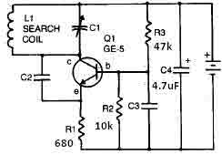
The metal detector circuit operates by generating an electromagnetic field through the use of capacitors and transistors, which are essential components for signal processing. The variable capacitor C1 allows for tuning the circuit to different frequencies, optimizing the detection capability based on the metal's properties being searched. The use of a 365 pF variable capacitor is crucial as it can be adjusted to change the resonant frequency of the circuit, thus enhancing sensitivity to specific types of metals.
Capacitor C2, a 100 pF silver mica capacitor, is known for its stability and low loss characteristics, making it suitable for RF applications. This capacitor plays a significant role in maintaining the integrity of the signal being processed. Capacitor C3, with a value of 0.05 µF, serves to filter high-frequency noise, ensuring that the output remains clear and reliable. Meanwhile, capacitor C4, rated at 4.7 µF, may be used for coupling or bypassing applications, aiding in the stabilization of the power supply voltage across the circuit.
The transistor Q1, which can be an RCA SK3011 or an equivalent NPN transistor, acts as a switching or amplifying device. Its role is to control the current flow through the circuit, allowing for the detection of metal objects by amplifying the signal generated by the electromagnetic field. The choice of an NPN transistor is critical, as it provides the necessary gain and switching capabilities required for efficient operation.
The resistors in the circuit, while not specified in detail, are integral to setting the biasing conditions for the transistor, controlling current flow, and ensuring stable operation of the metal detector. Proper selection and configuration of these resistors are essential for achieving optimal performance and sensitivity in detecting metallic objects.
Overall, this metal detector circuit design emphasizes the importance of component selection and configuration, ensuring reliable operation and effective metal detection capabilities.This metal detector circuit needs to be powered using a 9 volts power supply ( DC) or a 9 volts battery. The C1 capacitor is a variable capacitor with a value of 365 pF, C2 is a 100pF silver mica capacitor, C3 is a 0.05 uF disc capacitor and the C4 is a 4.7 uF capacitor.
The Q1 transistor can be RCA SK3011 npn transistor or equivalent type and all resist.. 🔗 External reference
Related Circuits

This digital thermometer circuit diagram utilizes a common 1N4148 diode as the temperature sensor. The diode's temperature coefficient of -2 mV/°C is leveraged to create an accurate electronic thermometer. A digital multimeter is employed to display the measured temperature,...
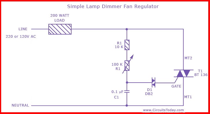
This is the circuit diagram of the simplest lamp dimmer or fan regulator. The circuit is based on the principle of power control using a Triac. The circuit operates by varying the firing angle of the Triac, which is...
This device can also be referred to as an economical hearing aid, as it can be constructed using low-cost components. Although its performance does not match that of advanced commercially available hearing aids, it can effectively assist individuals with...
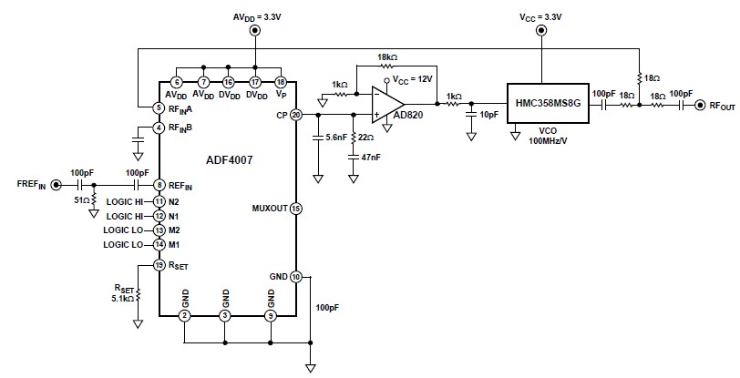
The ADF4007 high-frequency divider Phase-Locked Loop (PLL) synthesizer can be utilized in a variety of communication applications. It operates up to 7.5 GHz on the RF side and 120 MHz at the Phase Frequency Detector (PFD). The device includes...
This is a simple circuit designed for an audio amplifier project to control the speaker output relay. The purpose of this circuit is to manage the relay that activates the speaker output in the audio amplifier. The circuit is...
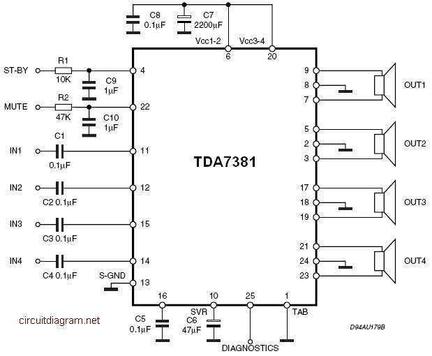
The TDA7381 is a Class AB audio power amplifier housed in a Flexiwatt25 package, specifically intended for car radio applications. This circuit can also be utilized for various other purposes. The fully complementary PNP/NPN output configuration enables a rail-to-rail...