
lamp dimmer circuit
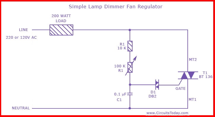
This circuit diagram illustrates a basic lamp dimmer or fan regulator, utilizing a Triac to control power delivery to the load. The fundamental operation hinges on adjusting the firing angle of the Triac, which is a semiconductor device that allows current to flow in both directions when triggered. The firing angle determines the duration for which the Triac remains conductive during each AC cycle, thus effectively controlling the average power supplied to the load.
In this configuration, R1 acts as a variable resistor, enabling the user to fine-tune the firing angle. By altering the resistance of R1, the phase angle at which the Triac is triggered can be modified, leading to changes in the power output. Resistors R2 and capacitor C2 play supportive roles in shaping the timing characteristics of the circuit, ensuring stable operation and appropriate triggering of the Triac.
The triggering mechanism involves Diac D1, which allows for a sharp turn-on of the Triac when the voltage across it reaches a certain threshold. This ensures that the Triac is activated at the desired firing angle, effectively controlling the load's brightness or speed.
When assembling the circuit, it is imperative to use a high-quality PCB or a reliable common board to ensure safety and performance. The design is limited to loads below 200 Watts; for applications requiring greater power, a Triac with a higher current rating must be selected to handle the increased load without risk of failure.
Safety precautions are crucial when working with this circuit, as all components are live during operation and can pose a shock hazard. Proper insulation, secure connections, and adherence to electrical safety standards are recommended to mitigate risks associated with high voltage and current.This is the circuit diagram of the simplest lamp dimmer or fan regulator. The circuit is based on the principle of power control using a Triac. The circuit works by varying the firing angle of the Triac. Resistors R1, R2 and capacitor C2 are associated with this. The firing angle can be varied by varying the value of any of these components. Here R1 is selected as the variable element. By varying the value of R1 the firing angle of Triac changes (in simple words, how much time should Triac conduct) changes. This directly varies the load power, since load is driven by Triac. The firing pulses are given to the gate of Triac T1 using Diac D1. Assemble the circuit on a good quality PCB or common board. The load whether lamp, fan or any thing, should be less than 200 Watts. To connect higher loads replace the Triac BT 136 with a higher Watt capacity Triac. All parts of the circuit are active with potential shock hazard. So be careful. >< Ini adalah diagram rangkaian dimmer lampu sederhana atau kipas sirkuit regulator. The didasarkan padaprinsip kontrol daya menggunakan sirkuit Triac. The bekerja dengan memvariasikan sudut penembakan Triac tersebut. Resistor R1, R2 dan kapasitor C2 adalah terkait dengan sudut tembak this. The dapat divariasikan dengan memvariasikannilai dari setiap R1 ini components. Here dipilih sebagai unsur variabel. Dengan memvariasikan nilai R1sudut penembakan perubahan Triac (dalam kata-kata sederhana, berapa banyak waktu harus Triac melakukan) changes.
Thislangsung bervariasi daya beban, karena beban didorong oleh pulsa menembak Triac. The diberikan ke pintu gerbangTriac T1 menggunakan D1 DIAC. Merakit sirkuit pada kualitas yang baik PCB atau beban board. The umum apakah lampu, kipas angin atau hal apapunharus kurang dari 200 Watts. To menghubungkan beban yang lebih tinggi menggantikan BT Triac 136 dengan Watt yang lebih tinggikapasitas Triac. Semua bagian dari sirkuit aktif dengan potensi kejutan hazard. So berhati-hati. 🔗 External reference
Related Circuits
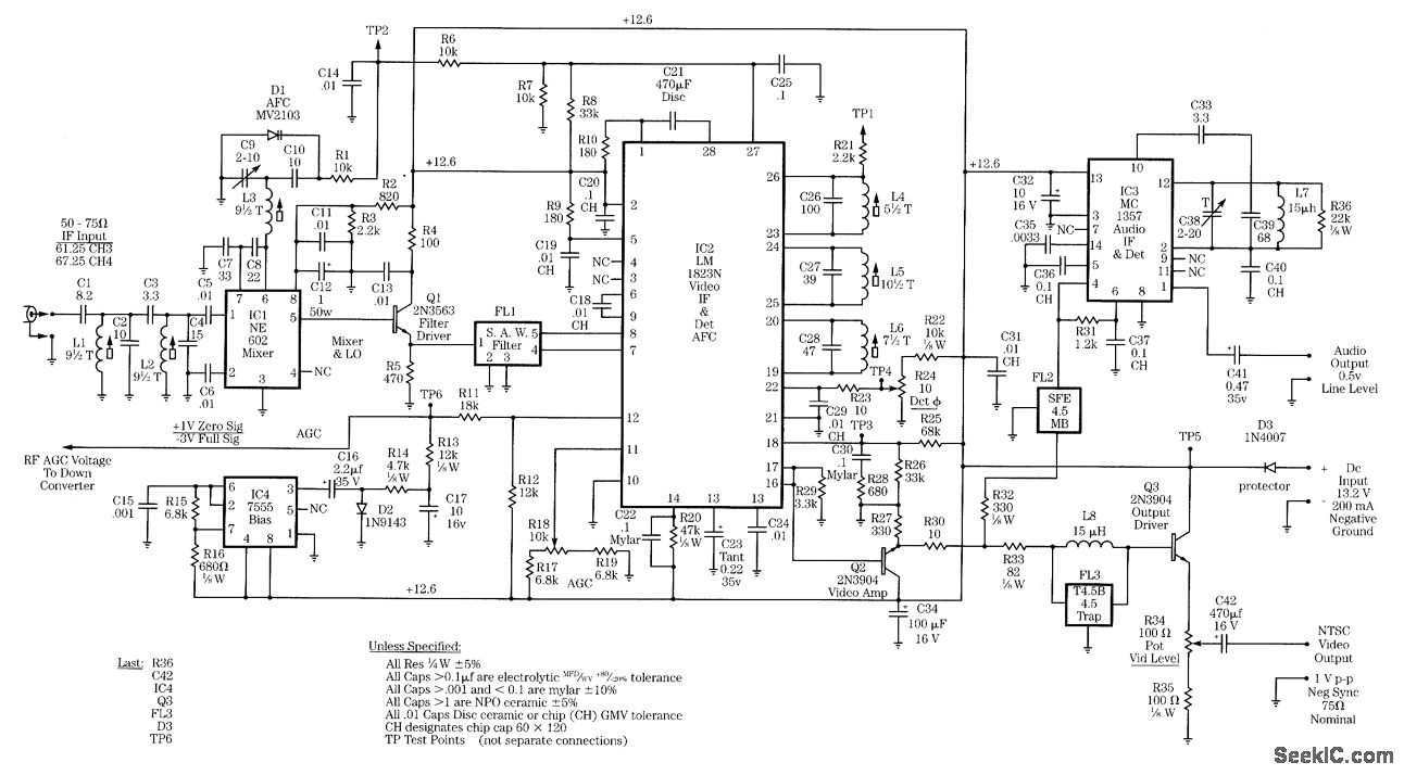
Radio-frequency schematics (also see NE602 datasheet and application note). This page contains electronic circuits related to RF receivers. This index features a broad collection of RF receiver circuits. Radio-frequency (RF) schematics are essential for designing and implementing circuits that operate...

This circuit generates inaudible ultrasound to create a barrier across an entry point. When the circuit detects a disruption in the sound barrier, it triggers a loud alarm to indicate the entry of a person. This system can be...
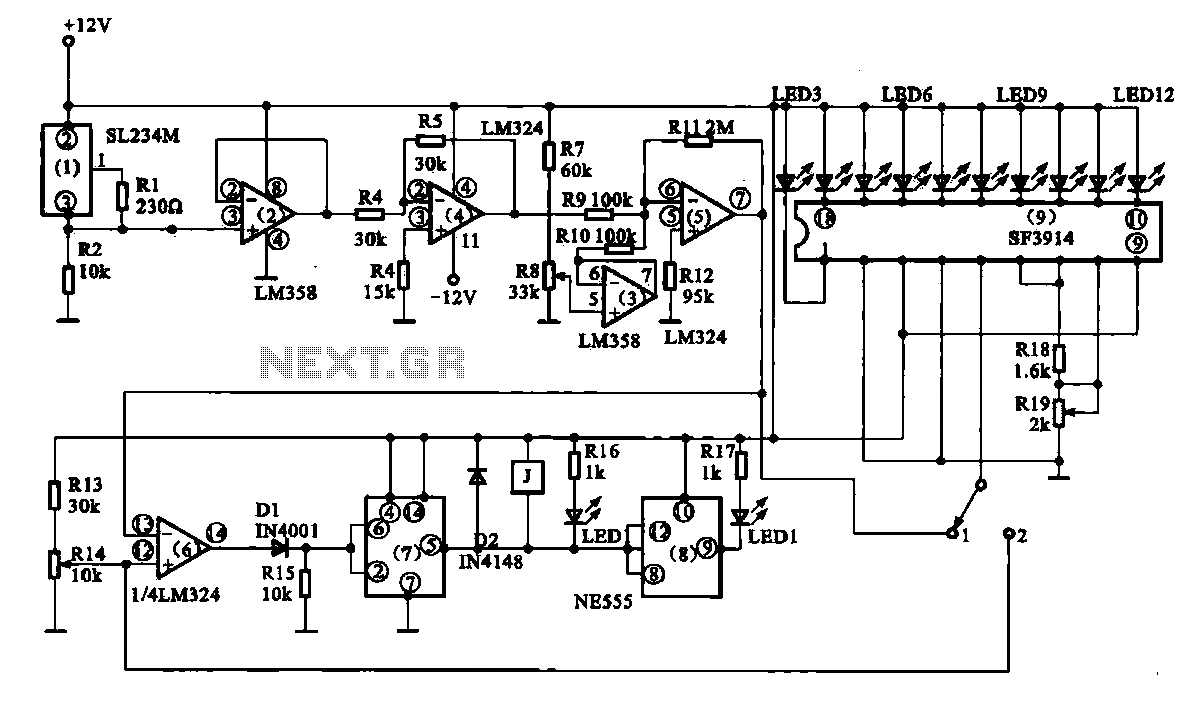
Vegetable greenhouse temperature detection control circuit. The greenhouse temperature detection control circuit is primarily composed of a temperature sensor SL234M, operational amplifiers LM324 and LM358, a dual time base circuit NE555, a relay, and a display driver circuit. The...
The provided schematic diagram illustrates an LM741 light/dark sensor circuit, derived from the 741 Op-Amp Tutorial by Tony van Roon. The ECG128/NTE128 transistor can be replaced with any NPN transistor that meets the necessary gain and current specifications for...
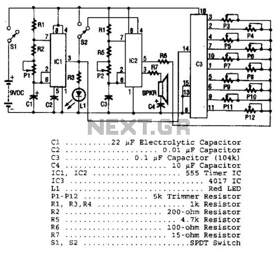
Three integrated circuits (ICs) are utilized to generate sounds. IC1 is a 555 timer configured as an astable multivibrator, producing clock pulses. The frequency of these clock pulses is adjustable via a trimmer potentiometer, P1. These clock pulses are...
All integrated circuits (ICs) are equipped with a 0.1 µF monolithic ceramic capacitor connected across their terminals. Additionally, each board features two capacitors: a 10 µF tantalum capacitor and a 100 µF electrolytic capacitor. The START BUTTON serves as...
Warning: include(partials/cookie-banner.php): Failed to open stream: Permission denied in /var/www/html/nextgr/view-circuit.php on line 713
Warning: include(): Failed opening 'partials/cookie-banner.php' for inclusion (include_path='.:/usr/share/php') in /var/www/html/nextgr/view-circuit.php on line 713