
Small Surround Sound Decoder

The surround sound decoder circuit functions by processing the stereo audio signals and distributing them into multiple channels to create an immersive audio experience. The circuit typically requires a power supply, operational amplifiers, and various passive components such as resistors and capacitors to ensure signal integrity and proper channel separation.
The input stage of the decoder accepts a standard stereo audio signal, which is then fed into a differential amplifier configuration. This stage is crucial for isolating the left and right audio channels. Following this, the circuit employs matrixing techniques to derive the center and rear channel outputs. The center channel is often generated by summing the left and right channels, while the rear channels may be created by applying specific filtering techniques to the stereo inputs to extract ambient sound information.
Additionally, the circuit may feature adjustable gain settings for each output channel to ensure balanced audio levels across the system. The use of high-quality capacitors and resistors can significantly affect the overall performance of the decoder, influencing factors such as frequency response and distortion levels. Proper grounding and layout considerations are also essential to minimize noise and interference, which can detract from the audio quality.
In summary, this surround sound decoder circuit is designed to enrich audio systems by transforming a standard stereo output into a multi-channel experience, enhancing the overall sound quality and immersion for the listener.This is surround sound decoder. With this circuit, you can divide the 2 channel (R and L channel) stereo output become 4 channel output that are R channel, L channel, Center out and Rear out. This circuit will enrich your audio sound system.. 🔗 External reference
Related Circuits

The generated alternating current (AC) at both ends of the voltage is adjusted after being rectified to supply the motor armature windings, allowing for speed adjustments of a 15W lamp. It is noteworthy that despite the freewheeling role of...
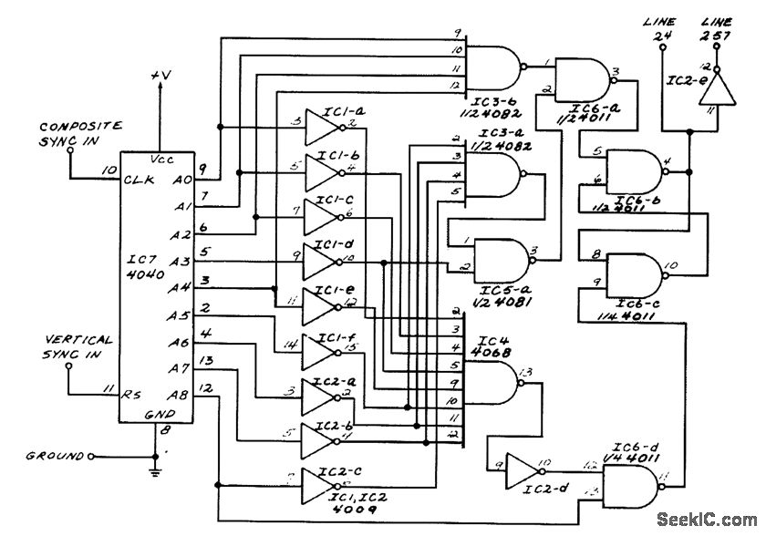
This circuit generates outputs on TV lines 24 and 257. It was utilized for a decoder circuit and employs a CMOS counter along with gate logic. Only one pin is designated for the output line indicator. The circuit described serves...
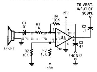
The receiver is an audio amplifier connected to SPKR1, a piezo speaker utilized as a microphone. An oscilloscope or headphones can serve as a detector. The oscilloscope can be triggered horizontally by the transmitted acoustic pulse, while the vertical...
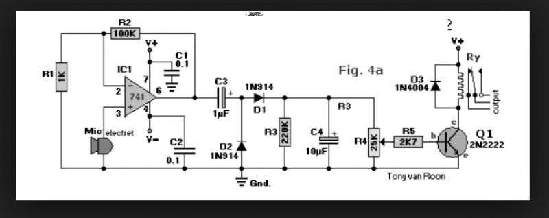
A circuit that enables control of a relay in response to sound from a non-amplified sound source, such as a computer, CD player, or a Digital Sound Recorder board. This circuit accepts audio input from any non-amplified sound source,...
This is one of my favorites. The LM386 is a low voltage audio power amplifier. It can provide 125mW to 750mW, enough for any project that uses audio. This circuit can work with batteries, requires minimum external parts and...
A one-chip computer has been utilized to design this survey meter, which directly displays the measured resistance on an LCD screen. The measurement range extends from 0 to 9999 kΩ, and the device can simultaneously store the measured data,...