
Acoustic Sound Receiver
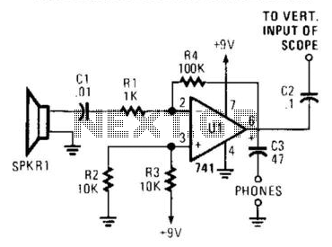
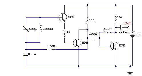
The described circuit features an audio amplifier functioning as a receiver, which processes signals obtained from SPKR1, a piezo speaker configured to act as a microphone. The piezo speaker is sensitive to acoustic waves, converting sound energy into electrical signals for further amplification.
The audio amplifier enhances the weak signals from the piezo speaker, enabling better detection and analysis of the received acoustic pulses. This amplification is crucial for applications that require precise measurement of sound waves, such as in distance measurement systems.
The system includes an oscilloscope or headphones as detection tools. The oscilloscope is particularly advantageous for visualizing the signals. It can be configured to trigger on the horizontal axis by the arrival of the transmitted acoustic pulse, allowing for a time-based analysis of the signal. The vertical axis displays the amplitude of the received signal, which correlates to the strength of the acoustic pulse.
Additionally, the delay time between the transmitted pulse and the received signal can be measured using the oscilloscope. This delay corresponds to the distance the sound wave traveled, which can be calculated using the speed of sound in the medium. This setup is useful in various applications, including sonar systems, distance measuring devices, and acoustic research, where accurate timing and signal analysis are critical.
Overall, this circuit exemplifies a practical application of audio amplification and signal detection, facilitating precise measurements and analyses of acoustic phenomena. The receiver is an audio amplifier fed by SPKR1, a piezo speaker that is used as a microphone. A scope or headphone s can be used as a detector. The scope can be triggered horizontally by the transmitted acoustic pulse; the vertical display can be used to drive the delay time, and hence the distance. 🔗 External reference
Related Circuits
The circuit schematic is straightforward. Information regarding the assembly and testing of circuits is not provided, as there are many instructional resources available. The circuit schematic in question is designed to be simple and user-friendly, allowing for ease of understanding...
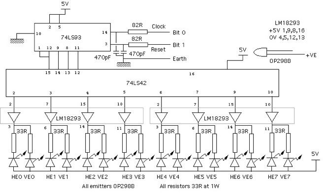
The design of a Sound Square appears straightforward; it requires several infrared beams across an opening. When a hand interrupts one of the beams, the system detects which beam is broken, allowing for the determination of the hand's position,...
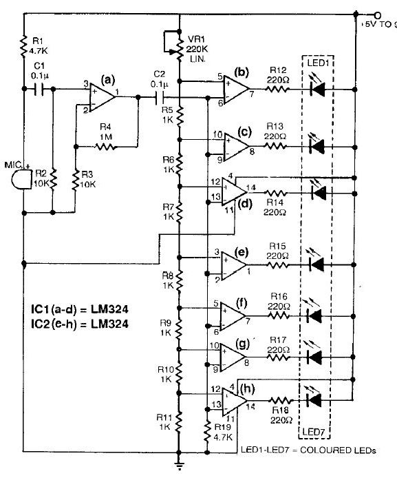
This sound level meter circuit can be used to control the intensity of a sound recording or in a disco. It has 5 measurement domains between 70 and 120 dB. The sound level meter circuit is designed to measure sound...
This sound-controlled lighting circuit design is utilized to adjust the brightness of connected lights in synchronization with captured sound. The sound-controlled lighting circuit operates by detecting audio signals through a microphone or sound sensor. The circuit typically consists of several...
This sound-activated switch allows for control through sound, which can be beneficial not only in robotics but also in home automation applications. The sound-activated switch operates by detecting specific sound frequencies or patterns, typically using a microphone or a sound...
This is a compact three-transistor regenerative receiver with fixed feedback. It is similar in principle to the ZN414 radio IC, which is no longer available. The design is simple, and the sensitivity and selectivity of the receiver are good....