
sound activated relay

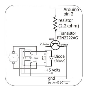
This sound-activated relay control circuit is designed to respond to audio signals from various non-amplified sources. The core components of the circuit include an electret microphone, a relay, a capacitor (C2), and a biasing resistor (R1).
The electret microphone converts sound waves into electrical signals, which are then processed by the circuit. The internal FET of the electret microphone requires a bias voltage to function correctly, which is provided by resistor R1. The choice of R1 affects the microphone's sensitivity, allowing for adjustment based on the specific application and environment.
Capacitor C2 plays a crucial role in determining the relay's activation duration. Initially, when power is supplied to the circuit, C2 charges and causes the relay to energize. The time it takes for the relay to deactivate is influenced by the capacitance value of C2. For applications where a longer activation period is desired, a larger capacitance can be used, while a smaller capacitance will result in a quicker deactivation. However, care must be taken not to exceed the maximum capacitance of 47 µF to ensure proper circuit functionality.
The relay itself is a switching device that can control higher power loads, such as lights or other electrical devices, based on the sound input. When the audio signal reaches the predetermined threshold, the relay closes, allowing current to flow to the connected device. This enables the device to be turned on or off in response to changes in sound volume, providing a practical solution for sound-activated control applications.
In summary, this circuit offers a versatile and adjustable method for controlling electrical devices through sound, making it suitable for various applications in automation, entertainment, and interactive installations. Proper component selection and configuration are essential for achieving the desired sensitivity and response characteristics.A circuit that allows you to control a relay in response to sound from a non-amplified sound source (computer, CD player, or my Digital Sound Recorder board). This circuit accepts audio input from any non-amplified sound source and when the volume reaches a certain level, it actuates a relay.
This relay can be used to switch another device
(light bulb, etc. ) on and off in sync with the volume of the input. The circuit can work from any 5 12 VDC regulated power supply provided a relay with the suitable coil voltage is used. When you first connect the supply voltage to the sound activated switch circuit, the relay will be energised because of the effect of capacitor C2.
Allow a few seconds for the relay to be switched off. You can increase or decrease the on` period by changing the value of C2. A higher value results in a longer on` period, and vice versa. Do not use a value greater than 47 F. Biasing resistor R1 determines to a large extent the microphone sensitivity. An electret microphone usually has one internal FET inside which requires a bias voltage to operate. The optimum bias level for response to sound has to be found by trial and error.
Related Circuits
The aquarium design utilizes a DPDT relay and a 12V inverter. The selected relay is rated adequately for a 400-watt load. The 12V DC relay, transformer, and diodes consume minimal power, making efficiency a minor concern. It is unclear...
Extended periods of bright sunshine and warm weather can cause even large storage batteries in solar power systems to become quite warm. Therefore, a circuit is typically connected in parallel with the storage battery to either engage a high-power...

This circuit is designed to activate a relay in response to low light conditions, meaning the relay will engage when the light intensity drops below a specified threshold. In the absence of hysteresis, the relay will turn on and...
To control the motor, an H-bridge will be utilized in conjunction with a double-pole double-throw (DPDT) relay, as illustrated in the schematic below. For further details, additional resources are available. The proposed circuit employs an H-bridge configuration to facilitate bidirectional...
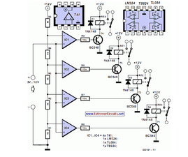
This circuit demonstrates that microprocessors, personal computers, and the latest ultra-accurate digital-to-analog converters (DACs) are excessive for the task of sequentially controlling four relays. The circuit utilizes a simple microcontroller or a basic timer IC to manage the operation of...
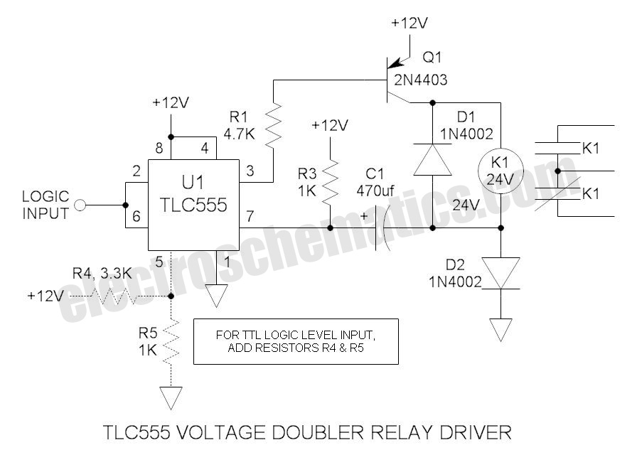
These novel relay driver circuits can activate a relay with a coil voltage rating that is double the Vcc. After activation, the relay armature is held in place. The relay driver circuits described are designed for applications requiring the control...