
Making A Simple Joule Thief circuit

The joule thief circuit is designed to operate efficiently with low input voltage, typically from batteries that are no longer able to power conventional devices. The fundamental components of a joule thief include a transistor, a resistor, a transformer (or inductor), and an LED.
The circuit operates by using the transistor as a switch, rapidly turning on and off to create a feedback loop that generates a higher voltage across the transformer. When the transistor is turned on, current flows through the primary winding of the transformer, building up magnetic energy. Once the transistor turns off, the magnetic field collapses, inducing a higher voltage in the secondary winding, which is then used to power the LED.
To construct a basic joule thief, the following components are typically required:
1. **Transistor**: A small-signal NPN transistor (such as 2N3904 or BC547) is commonly used.
2. **Resistor**: A resistor (around 1kΩ) is used to limit the base current to the transistor.
3. **Inductor**: A toroidal core inductor or a bifilar wound transformer with a primary and secondary winding.
4. **LED**: A light-emitting diode that will be powered by the circuit.
5. **Power Source**: A weak or nearly depleted battery, such as a single AA or AAA cell.
The assembly involves connecting the components in the following manner:
- The collector of the transistor connects to one end of the primary winding of the transformer.
- The other end of the primary winding connects to the positive terminal of the battery.
- The emitter of the transistor connects to the negative terminal of the battery.
- A resistor is placed between the base of the transistor and the positive terminal, while the secondary winding of the transformer connects to the LED.
This simple yet effective circuit exemplifies how low-voltage energy can be harnessed for practical applications, promoting sustainability and efficient energy use. The joule thief can be used in a variety of projects, including as a flashlight or in other low-power LED applications, showcasing its versatility and utility in electronics.Today I am showing you how to make a very simple joule thief. A joule thief has many applications, the best gadget that I made with was a Water Powered Lamp, soon Im going to post on a guide about it but first I need to post this guide. I used an iPhone 4S as my camera. To simplify everything, a joule thief is a circuit that helps drive an LED light even though your power supply is low. What can we do with it? We can use it to squeeze the life out of our old, almost drained, non functioning batteries. This project can also be considered as a green and environmental experiment, we can also use it as a flashlight that can be ran by an old, weak, almost drained battery.
🔗 External reference
Related Circuits
This is a very simple crystal receiver circuit for short wave band and can be used with headphones. The described circuit is a basic crystal receiver designed to operate within the shortwave frequency band. The primary components of this circuit...
A wide range auto turn OFF timer covering 1 minute to 20 hours in three ranges with S1. As soon as power is applied to the circuit, the IC1 [555] starts to oscillate and feeds clock pulses to the...
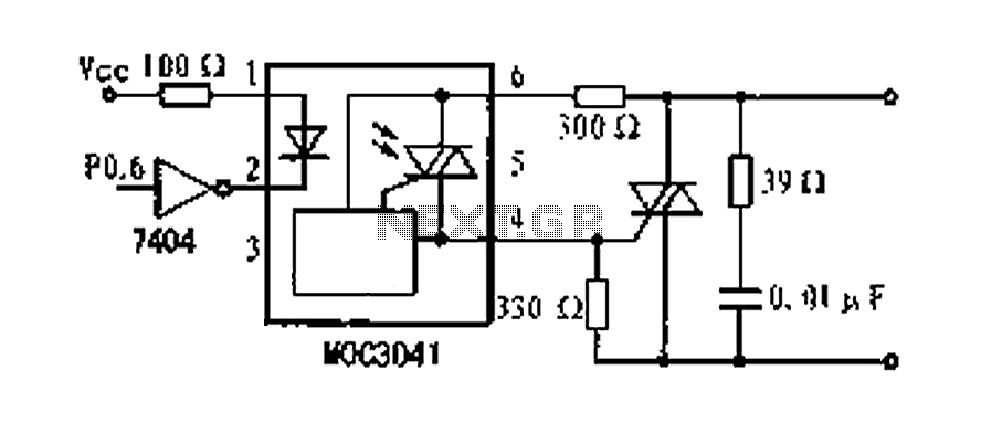
A dimming control circuit is implemented using a single-chip I/O port sinking method to control a thyristor switch for dimming functionality. The MOC3041 optocoupler features an internal zero-crossing detection circuit, allowing for effective control of the thyristor. This design...
This HD TV UHF wideband amplifier (Ultra High Frequency amplifier) provides a total gain of 10 to 15 dB within the frequency range of 400 to 850 MHz, making it suitable for areas with weak television signals. To ensure...
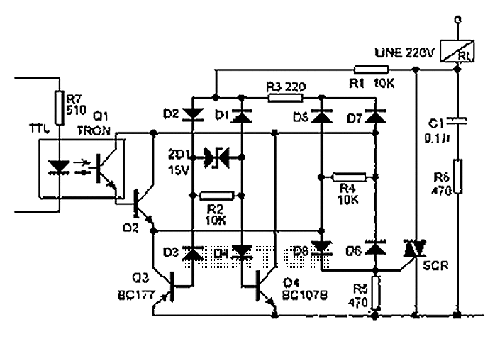
The relay illustrated in the figure operates based on non-inductive analog circuit theory. Its working principle involves a 220V power supply connected to a load (RL), resistors (R1, R3, R6), diodes (D1 to D8), and a zener diode (ZD1)....
This circuit utilizes the widely available LM3914 integrated circuit (IC). The LM3914 is straightforward to operate, does not require external voltage regulators due to its built-in voltage regulation, and can be powered from nearly any voltage source. This makes...