
SMPS circuit
The flyback tester circuit employs an astable multivibrator configuration, which allows it to oscillate continuously without requiring any external triggering. The core components typically include two transistors, resistors, capacitors, and a transformer. The transistors are configured to alternately switch on and off, creating a square wave output that drives the primary winding of the transformer. The frequency of oscillation, around 90 kHz, is determined by the values of the resistors and capacitors in the circuit.
In practice, the circuit is powered by a 12 V DC supply, which is connected to the collector of the first transistor. The output from the secondary winding of the transformer is connected to the input of the circuit, allowing for testing of various transformer configurations. The voltage measurement at the primary winding can be performed using an AC voltmeter, which will indicate the output voltage generated by the oscillation in the transformer. A successful measurement will show a voltage within the specified range, confirming the operational integrity of the transformer.
In cases where the primary winding does not produce any voltage, further investigation is required, as this may suggest a fault in the transformer. The circuit can be modified to accommodate different transformer specifications by adjusting component values or transformer connections, making it a versatile tool for testing a wide range of transformers in electronic applications.Its a simple fly back tester, I believe you can built it, i use this circuit to test all of high freq transformer like SMPS transformer or fly back, this circuit is an astable multivibrator with about 90Khz freq, 12 vdc as vcc. To check SMPS transformer or fly back you should reverse the input and output, i mean you use secondary 12v or 24v out pu
t as input, give 12 or 24 output pin 12 vdc and another pin to output this circuit, when you turn on this circuit, use ac volt meter to measure primary, it should be come out 80 - 480 vac, depend to transformer spec, if there is no voltage come out from the primary transformer, so the transformer is damage, you can also measure another pin with the same step. 🔗 External reference
Related Circuits
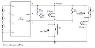
The values of the LM56 thermostat project circuit diagram for resistors R1, R2, and R3 at the travel points VT1 and VT2 can be determined using the following equations. This electronic circuit thermostat with the IC LM56 serves as...
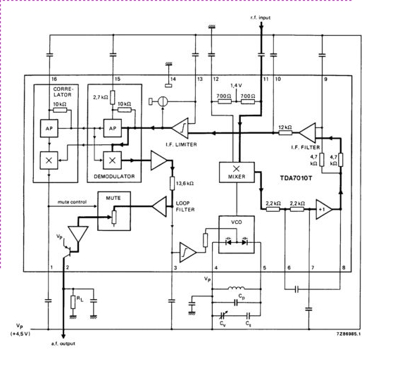
The TDA7010T is a monolithic integrated circuit designed for mono FM portable radios, emphasizing minimal peripheral components to achieve small dimensions and low costs. The IC features a frequency-locked loop (FLL) system. The TDA7010T is engineered to provide high-performance FM...
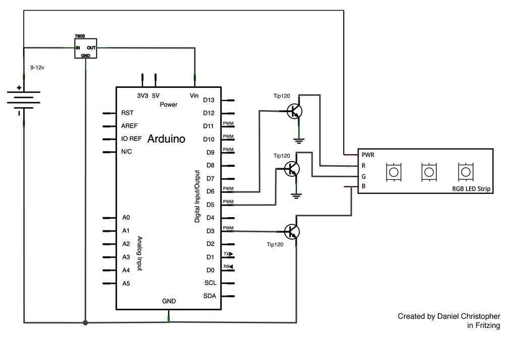
This document outlines the assembly of a circuit designed to pulse width modulate (PWM) a high-power RGB LED strip and program an Arduino to cycle through various colors. The high-power range is specified as 9-12 volts. The procedure includes...
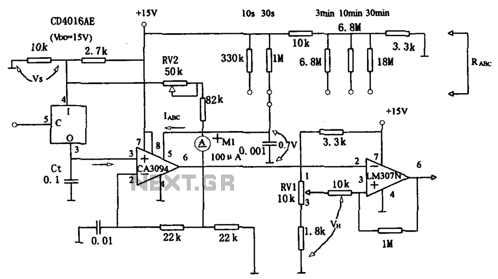
The long timer circuit utilizes an operational amplifier, specifically the CA3094, to control the discharge formula for extended timing. This is typically achieved by adjusting the variable resistor RV1, which alters the timing duration to meet specific requirements. The long...

This circuit is designed for general-purpose use with a large LED display utilizing SPI serial interfacing. It employs a serial-in-parallel-out shift register, specifically the 74HC595, to receive serial data from a microcontroller board. The schematic wiring indicates that SER...
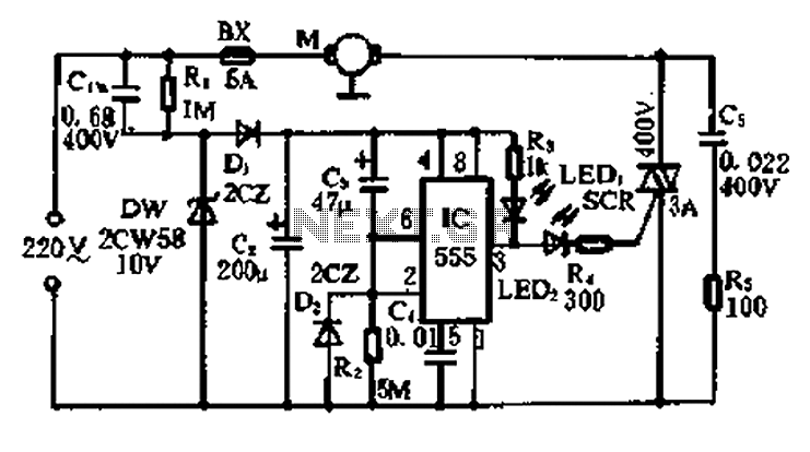
A 5-minute circuit can continue to operate during a power outage, providing protection for the refrigerator. The refrigerator power protection circuit, designated as 1136, includes a power transformer that converts 220V voltage through a rectifier bridge (VD1). This setup...