
DC generator automatic voltage regulator circuit
The DC generator automatic voltage regulator circuit is a critical component in maintaining stable output voltage in a 40kW, 230V DC shunt complex machine. The circuit operates by monitoring the output voltage and making necessary adjustments to ensure that it remains within specified limits, with a voltage change rate of no more than 2.5 percent.
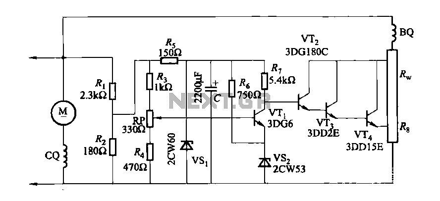
In the schematic, the shunt winding (BQ) is connected to the generator's output terminals, which allows it to sense the voltage level. The series winding (co) is incorporated into the circuit along with an external shunt resistor (Rw), which is essential for controlling the overall voltage feedback loop. The presence of the series winding aids in improving the response time of the voltage regulation, especially during load variations.
The adjustment potentiometer (RP) plays an important role in the regulation process. By varying the resistance through this potentiometer, the operator can set the desired output voltage level. This capability is particularly useful during initial setup or when the load conditions change significantly, allowing for fine-tuning of the generator's performance.
Overall, this automatic voltage regulator circuit is an essential feature for ensuring the reliable operation of the DC generator, providing both stability and flexibility in voltage management for various applications.DC generator automatic voltage regulator circuit is shown in Figure 7-53. This circuit is used to 40kW, 230V DC shunt complex machine, the voltage change rate up to 2.5 percent . In Figure 7-53, BQ for the shunt winding, co} for the series winding in series with the external shunt resistor Rw winding circuit. Adjustment potentiometer RP, can change the generator output voltage setpoint.
Related Circuits
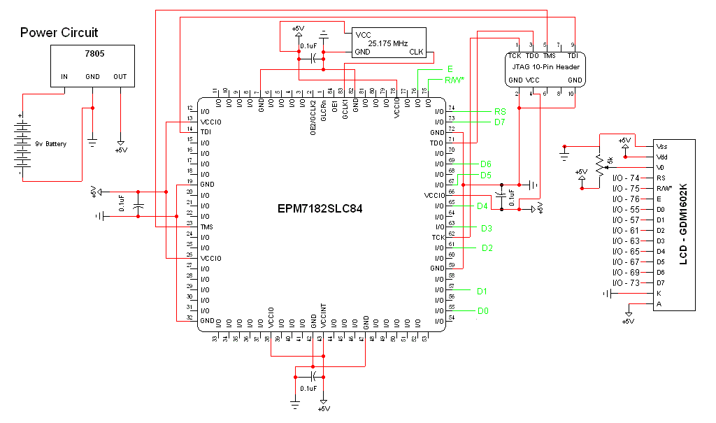
The schematic for this project is a modified version of the CPLD development board schematic. Several new components have been added for this project, and the completed schematic is presented below. The primary components in the schematic include the...
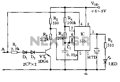
The electronic pest-killing lamp circuit comprises an oscillator, control circuit, high voltage generator, LED indicator circuit, and power supply circuit. The schematic diagram illustrates these components. The oscillator circuit includes a time-base integrated circuit (IC), resistors R5 to R7,...
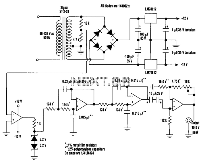
A highly stable 60-Hz sine wave can be delivered with this circuit, which offers a different and much simpler approach to achieving a stable amplitude. Capacitor coupling in the last stage removes any DC component caused by unequal Zener...
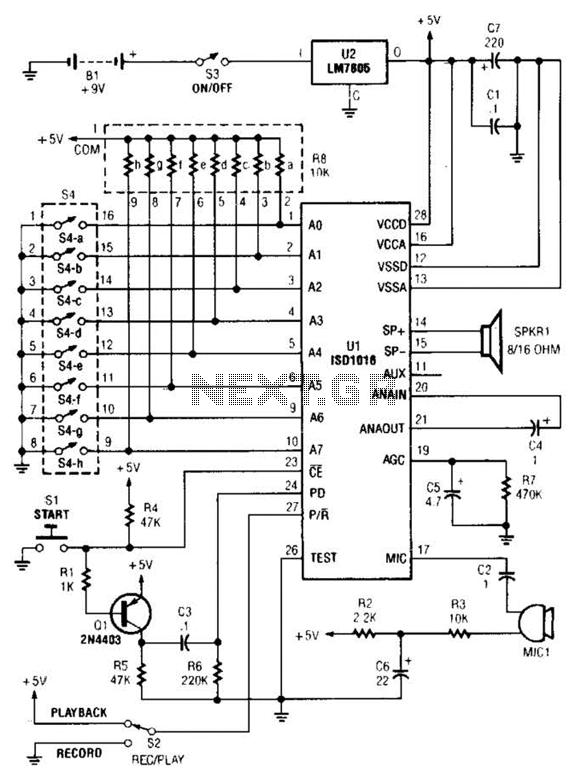
The personal message recorder is based on the ISD1016 CMOS voice messaging system, eliminating the need for complex and costly analog-to-digital and digital-to-analog conversion circuits. A functional block diagram of the ISD1016 is available. The ISD1016 integrates all necessary...
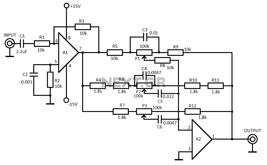
This 3-band equalizer circuit is an active filter network designed to adjust bass, midrange, and treble audio frequencies. It utilizes the LM833 operational amplifier from National Semiconductors, which is known for its very low noise figure and wide frequency...
The circuit utilizes a 555 timer along with resistors R4, R5, and capacitor C1 configured in a controllable multivibrator mode. This setup forces the reset terminal (pin 4) to a specific state, allowing for control of the external logic...