
RF Field Strength Meter Circuit
The RF field strength meter circuit typically consists of an input stage, amplification stage, and output stage. The input stage includes an antenna that captures the RF signals from the environment. The dual MOSFET configuration serves as the amplification stage, where the first MOSFET amplifies the weak RF signal received by the antenna. The second MOSFET further enhances the signal strength, ensuring that the meter can accurately measure low-power signals.
The adjustment of amplification via potentiometer P1 allows users to fine-tune the sensitivity of the meter, enabling it to respond appropriately to varying signal strengths. This feature is particularly beneficial in environments where signal conditions can fluctuate.
The switch S1 is strategically placed to allow the user to select among three predefined frequency ranges, which caters to different operational needs in the field. This flexibility ensures that the meter can be used effectively across various applications, from amateur radio communications to tuning radio-controlled models.
The output stage typically includes an analog or digital readout that provides a clear indication of the field strength. This readout is crucial for users to determine the effectiveness of their antenna alignment and the operational range of their radio controllers.
Overall, the RF field strength meter is a critical tool for hobbyists and professionals alike, enabling precise measurements and adjustments in radio frequency applications. Its design emphasizes sensitivity and versatility, making it an essential device in the field of radio communications.A sensitive and reliable rf field strength meter is an invaluable instrument in amateur radio and in radio controlled model area. A field strength meter is used to align an antenna to get the best possible gain, to determine the transmitting range of radio controllers Designing the rf field strength meter to be sensitive it is a requirement be
cause there must be as many wavelengths as possible between the meter and the transmitter, the measurement can be done without using a stronger carrier signal and most of the radio controllers are of low power type. Considering these factors, a dual MOSFET is used as an RF amplifier in this circuit. The amplification can be adjusted by P1 and with S1 switch we can select three frequency ranges: 🔗 External reference
Related Circuits
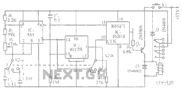
A 100 second delayed turn ON relay RL1 switch, if plug power +12V in circuit. In Fig.2 see a two range 6-60 second and 1-10 minute auto turn off relay timer circuit, with 555. Part List R1=1 Mohms C4=100nF...
Ensure to verify all connections utilizing the circuit diagram and breadboard schematic available for download from the provided links. This resource can assist during the assembly process. To create a reliable electronic circuit, it is essential to meticulously verify all...
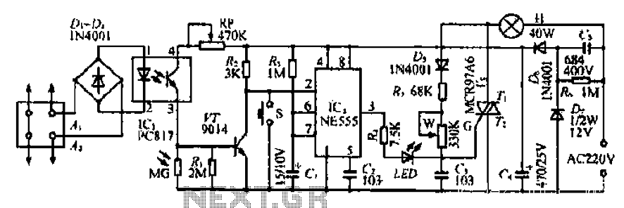
The Ai. A2 series operates with a telephone line, where sound anomalies or off-hook currents activate a light within an arc tube, which in turn triggers a photosensitive MOSFET. This process involves a saturated conduction base voltage that sends...
The system operates between 10 minutes to 2 hours, featuring a 100-line bell controlled by a multi-gear stick labeled S2 41f. The integrated circuit (IC) functions as a self-excited multivibrator. The device can manage binary pulses ranging from 3...
The technical parameters of high-speed optocouplers include a rise time (t1) of less than or equal to 300 ns, a circuit transfer ratio (CTR) of 50%, an isolation voltage (VSO) of at least 15,000 V, and an output transistor...
The video master comprises a series of converters that allocate all video sources to unused UHF channels. These channels are then combined with standard TV channels, whether terrestrial or cable, into a single cable. This single cable can subsequently...