
Solar Battery Regulator/Controller
The described electronic circuit is a battery management system designed to optimize the charging and discharging of lithium and lead-acid batteries. The use of the LM4041 voltage reference ensures a stable 1.225V reference voltage, critical for accurate voltage measurements across different battery chemistries. The circuit employs a voltage divider configuration, allowing for the selection of appropriate voltage levels for sealed lead-acid and lithium batteries, while maintaining tolerance levels that prevent overcharging.
The load management is handled through the IRF350LC MOSFETs, capable of switching high currents exceeding 10A, which is essential for applications requiring significant power. The inclusion of hysteresis in the load switching mechanism prevents rapid cycling of the load state, thereby enhancing the reliability of the system under varying solar charge conditions. Additionally, a dual CMOS rail-to-rail op-amp simplifies the voltage switching calculations, providing flexibility in the design.
The system architecture supports the connection of external batteries, with an internal DIP switch allowing for the selection of battery type, ensuring compatibility with various battery technologies. This feature is particularly useful for users who may need to switch between lithium and lead-acid batteries. The design prioritizes low power consumption, allowing for energy accumulation even in low-light conditions.
The battery configuration consists of three 3.6V lithium cells in series, creating a nominal voltage of 10.8V, with the potential for parallel banks to increase capacity. The charge cycle voltage range is carefully managed to prevent damage to the cells, with a maximum on-charge voltage of 12.3V and a minimum discharge threshold of 9.0V. This design consideration ensures that the batteries can be safely used with standard 12V solar panels while protecting against over-discharge during operation.
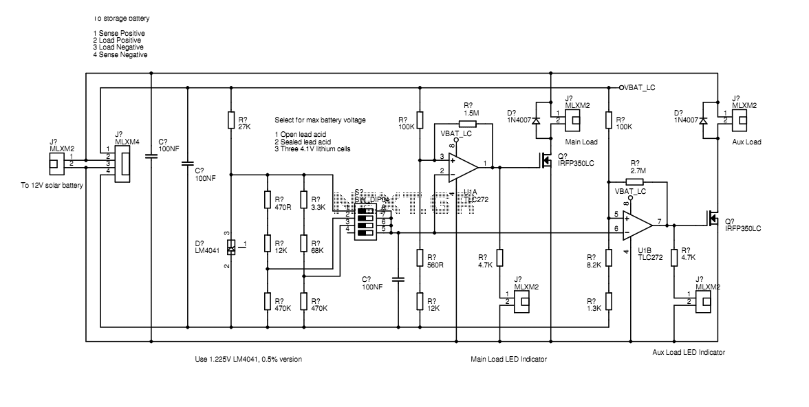
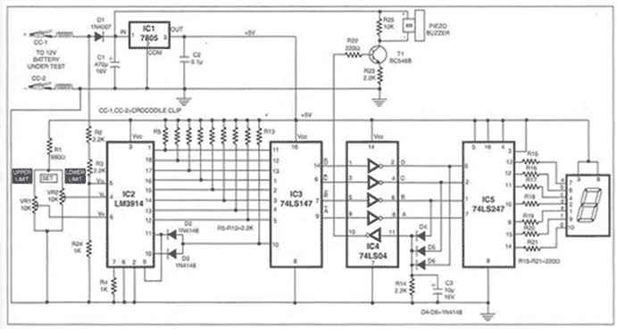
Overall, the circuit is engineered for efficiency and safety, making it suitable for a variety of applications requiring reliable battery management in solar-powered systems. The absence of temperature compensation for lead-acid batteries is a notable design consideration, emphasizing the importance of maintaining operational temperatures within specified limits to avoid overcharging risks.In the actual device the transistors are bolted to the aluminium case. The schematic diagram shown here represents how the circuit would be built if all components were on-board. Separate paths for load current and voltage sensing allow the battery voltage to be measured accurately even under loads of several amps.
The LM4041 provides an accurate low-power voltage reference for the sensing circuit. This 1.225V reference is used directly for the conventional lead-acid setting and via two alternative dividers for the sealed lead acid and lithium voltages. Using a 1% version for the voltage reference and 1% resistors in these dividers keeps us from going too far above the magic 4.1V limit on standard lithium cells without having a pesky trimmer, or worse, a set of trimmers.
As the voltage across the battery rises under charge, the main load output will be switched on when a voltage some way above the fully discharged level is reached. If the load current exceeds the available solar charge current, the batteries will drain back down to the fully discharged state and the load will be disconnected again.
Some hysteresis avoids the load switching on and off too frequently, but this all depends on the available charge current, battery capacity and load current. If the charge current exceeds the load, the battery voltage will continue rising until the full charge voltage is reached.
At this point the secondary load is turned on to prevent overcharging. If no secondary load is naturally available, one must be provided in the form of a resistor. If the standard load current exceeds the maximum output of the solar array this is not needed. IRF350LC MOSFETS are used for load switching which allows loads of more than 10 amps to be switched. A dual CMOS rail-to-rail output op-amp is used which simplifies the calculation of the switching voltages. LED indicators drawing about 2mA each show which loads are turned on. There is space inside the regulator enclosure for about 7Amp-Hours worth of surplus mobile phone lithium batteries.
Three 3.6V nominal voltage cells are wired in series which produces a battery of 10.8V, then multiple banks of three are wired in parallel. The voltage varies over the charge cycle from 3 X 3.0 = 9.0V when fully discharged to 3 X 4.1 = 12.3 V which is the maximum allowable on-charge voltage.
Higher voltages will destroy these cells. The 12.3V maximum charge voltage allows the battery to be charged from 12V solar panels and the 9.0V full discharge voltage allows most non-critical 12V equipment to run the batteries right down to empty without over-discharging them. An external battery can be connected if needed but if it is a different technology the internal one must be disconnected first.
The external battery may be lithium as described, conventional lead acid, or sealed lead acid and the appropriate voltages are selected on an internal DIP switch. The circuit is designed to draw very little current so that some charge can be accumulated even when the weather is quite dull.
If lead acid batteries are used then its worth noting that there is no temperature compensation on the charge voltages, so it's best to keep them between 10 and 30 degreesC or the -2mV/K coefficient of this technology might result in overcharging of sealed gel units. 🔗 External reference
Related Circuits
Using a transistor will not yield accurate results, and the adjustment process can become quite tedious. The circuit is technically correct; if the tripping point can be adjusted properly, it may function as intended. Vinod states that he created...
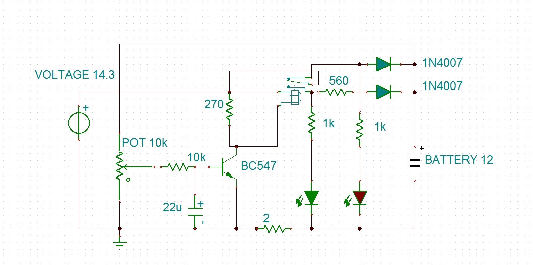
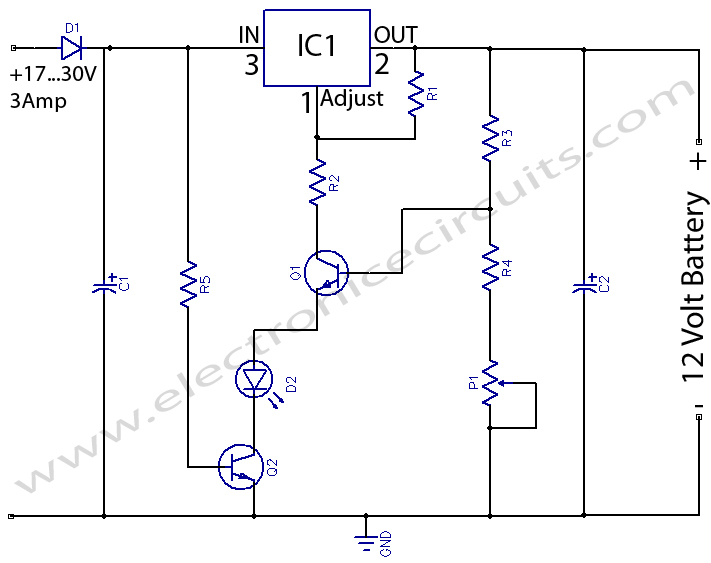
This circuit outputs a voltage of 14 volts with a maximum current of 4A. It can be used for NiCad batteries and accumulators, both wet and dry types. However, the accumulator must be rated for 12 volts and have...
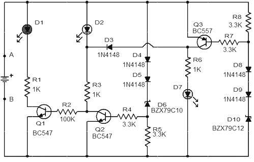
When the battery voltage is 11.5V or less, transistor Q1 is activated, and LED D1 will illuminate. When the battery voltage is between 11.5V and 13.5V, transistor Q2 is activated, causing LED D2 to light up. At a battery...
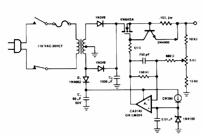
A battery is a crucial component of any battery-backed system. Often, the battery is more costly than the system it supports. Therefore, it is essential to implement all practical measures to extend battery life. According to manufacturer data sheets,...
This charger will quickly and easily charge most any lead acid battery. The charger delivers full current until the current drawn by the battery falls to 150 mA. At this time, a lower voltage is applied to finish off...
12 Volts Lead Acid Battery Charger Circuit. Apart from serving as a standard battery charger, this circuit is ideal for providing a constant charge to a 12-Volt lead-acid battery. This 12-Volt lead-acid battery charger circuit is designed to efficiently charge...