
modified battery charger circuit
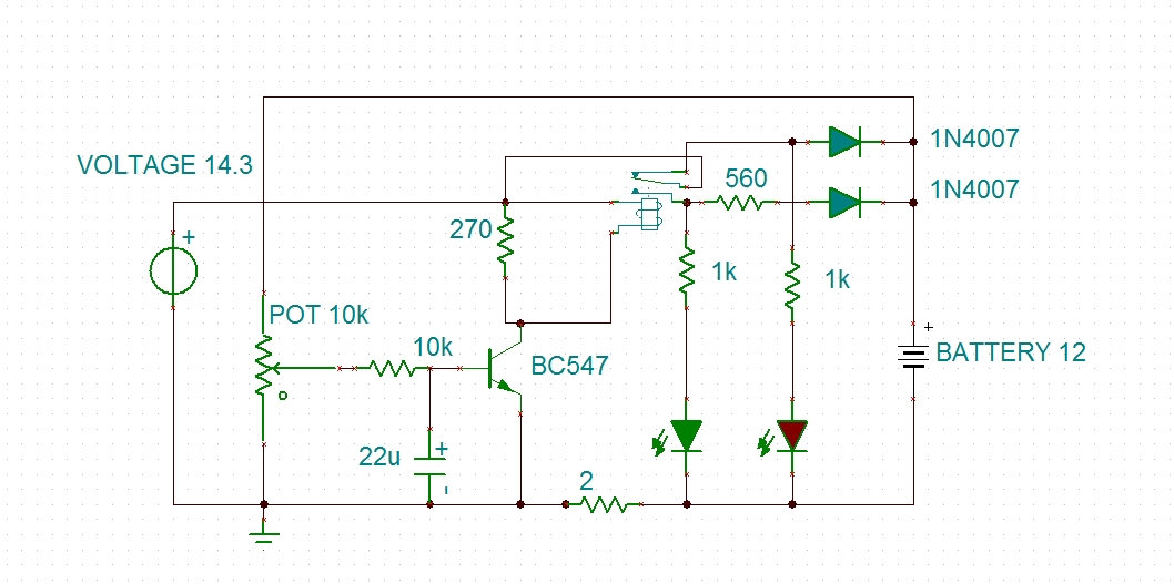
The described circuit involves a hysteresis charger designed to manage the charging of a battery effectively. The primary components include a transistor, a relay, a diode (D6), a current-limiting resistor, and LED indicators. The transistor functions as a switching device to control the charging current based on the battery voltage level. The hysteresis feature allows for a stable transition between charging states, preventing rapid on-off cycling that could lead to inefficiencies or damage to the battery.
The initial observation of a voltage discrepancy suggests that there may be an issue with the circuit configuration or the measurement technique. When the multimeter indicates a voltage of 16.8V while connected to the circuit, it may imply that the charger is outputting a voltage influenced by the transient response of the circuit or an incorrect measurement setup. Disconnecting the battery and measuring again to observe an output of 14.2V indicates that the charger operates correctly under no-load conditions, but the presence of the battery alters the circuit dynamics.
The relocation of the green LED and resistor R1 after diode D6 could impact the feedback mechanism of the circuit, potentially affecting the voltage regulation. It is crucial to maintain the integrity of the feedback loop for accurate voltage regulation. The relay's output, delivering a clean voltage of 13.9V (0.033A), suggests that the circuit is capable of providing stable output under specific conditions.
To ensure proper functionality, it is advisable to verify the multimeter's calibration and confirm that the probes are correctly positioned during measurements. Further adjustments to the tripping point may be necessary to achieve the desired performance of the charger. The design allows for monitoring the charging process through LED indicators, which provide visual feedback on the charging stages, enhancing user experience and ensuring safe operation.Using a transistor won`t give accurate results, moreover the setting part would become very tedious. The circuit is technically correct, if you can adjust the tripping point correctly, then it might just work. Vinod: I made the charger (hysteresis) but there is a problem. i will attach the image to explain the problem. When i connect multimeter in that particular red dots, the voltage shows 16. 8. (0. 43 A) but when i disconnect battery from the charger and measured again. then there is no problem. the out put is 14. 2. And the other pin of the relay(through the current limiting resistor) will deliver a clean output voltage of 13. 9 (0. 033A). Why this is happening. The only change i have made from this circuit is to grab the green LED and R1 from there and connect it after the D6.
Swagatam: It`s difficult to understand the fault, if you are the connecting meter prods across the battery terminals, it should show the average voltage of the battery and the supply voltage. not sure why it`s showing a higher voltage. Is your meter OK You can repeat the checking by switching OFF the power supply and then again switching ON the power supply keeping the meter connected to the points A and B.
Hi Swagat, Atlast i made a charger that suits my needs. this is the schematic. (plz look attachment). Until battery gets 13v this is a constant current charger(400-500mA). After 13v, charging current is 25mA. And the LED`s indicate the charging stages. Regards Vinod chandran 🔗 External reference
Related Circuits
This design is based on one published by Milan Lulic in the German magazine elektroModell. Mr. Lulic's design is for surface mount technology (SMT) construction, whereas mine uses standard off-the-shelf components, and is therefore better suited to construction by...
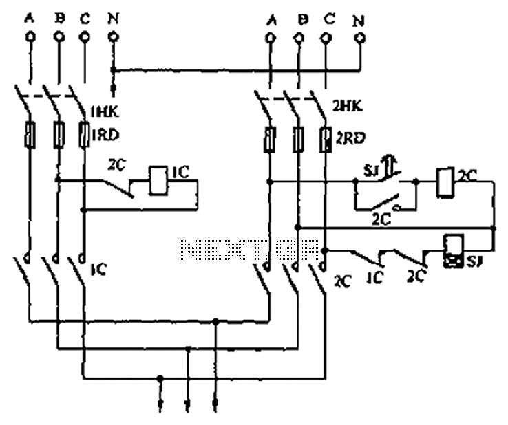
A dual three-phase power line circuit is illustrated in the figure. When the knife switches 1HK and 2HK are closed simultaneously, the normally closed contact 1C disconnects the power supply to the time relay SJ, allowing power to reach...
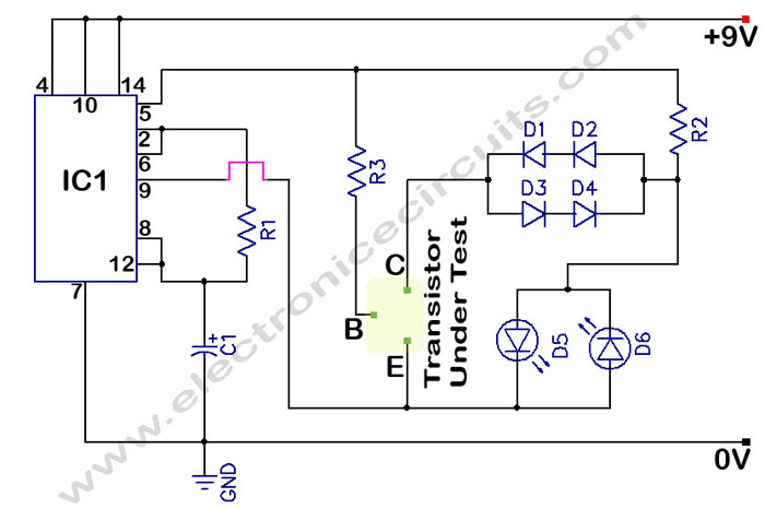
The circuit is a transistor tester schematic that indicates the condition of a transistor using two LEDs. It is designed to test a good NPN transistor. The transistor tester circuit operates by utilizing two light-emitting diodes (LEDs) to provide a...
This is a simple game circuit designed for multiplayer enjoyment. The objective is to score one hundred points within a limited timeframe. To restart the game, the S1 button switch must be pressed. It is important to ensure that...

A digital stopwatch or digital timer circuit schematic is constructed using the timer IC LM555 and the 4-digit counter IC MM74C926, which is paired with a multiplexed 7-segment LED display. The digital stopwatch circuit utilizes the LM555 timer IC configured...
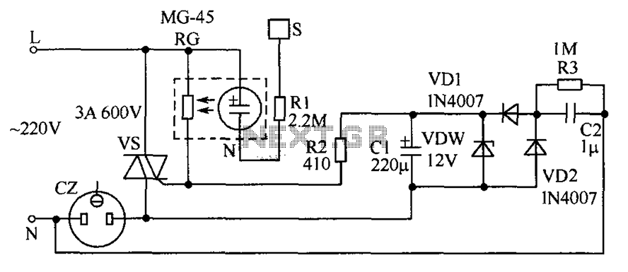
The circuit operates by detecting a finger touch on a metal sheet (S), which activates a neon tube light (N). The combination of the neon tube and a photoresistor (RG) acts as an optocoupler, reducing the resistance of RG....