
Car battery monitor circuit diagram

The circuit operates primarily as a car battery monitoring system, utilizing a series of transistors and LEDs to provide visual feedback on battery voltage levels. The use of transistors Q1, Q2, and Q3 allows for a clear indication of the battery's state, with each LED corresponding to specific voltage thresholds. The astable multivibrator configuration formed by Q1 and Q2 creates a flashing effect for the LEDs, which serves as an alert system for low battery conditions.
The adjustable resistor R4 enables customization of the voltage thresholds, ensuring that the system can be tailored to different battery types or user preferences. The inclusion of a NiCd battery charger circuit adds functionality, allowing users to maintain battery health while providing visual indicators of charging status. The overall design emphasizes efficiency and user-friendliness, making it suitable for automotive applications where monitoring battery health is crucial.
In addition to the monitoring capabilities, the circuit's design facilitates the powering of fluorescent lights from a battery, enhancing its utility in off-grid situations. This feature is particularly advantageous for users who require reliable lighting solutions in areas lacking electrical infrastructure. The blocking oscillator principle utilized in the voltage converter provides a robust mechanism for managing power conversion, ensuring stable operation across a range of input voltages.
Overall, this battery monitoring and charging circuit represents a comprehensive solution for managing automotive battery health, providing both visual indicators and charging capabilities in a compact and efficient design.When the battery voltage is 11. 5V or less transistor Q1 is turned on and the LED D1 will be bright. When the battery voltage is between 11. 5 and 13. 5 V, the transistor Q2 is turned on and the LED D2 will light up. When the battery voltage is 13. 5V transistor Q3 will be on the D3 and the LED will light. The schematic diagram come fro m circuit: Car Battery Monitor with 3 LED power supply. Go to that page to read the explanation about above power supply related circuit diagram. Car Battery Monitor circuit This is a circuit diagram of the 3 LED bar graph type battery monitor ideal for monitoring the voltage level of the car battery voltage with battery. When the battery voltage is 11. 5V or less. Here is a simple battery monitor circuit in which the LED will continue flashing until battery voltage is above the level.
Transistors Q1 and Q2 are wired as an astable multivibrator circuit. This flashing battery monitor circuit can operate from a variety of voltages from 6V to12V. The voltage level at which an LED stops flashing can be set by adjusting R4. When the a preset battery voltage reaches threshold flashing frequency decreases andwhen the voltage drops below the threshold of the diode D1 LED turns OFF. This is used to compensate for changes in voltage of the base emitter Q1 due the. This NiCd battery charger circuit is very simple but it has a current and voltage limiting. Lamp L1 will light brightly and the LED will be out when the nicd battery is low and being charged, but the LED will.
The following figure shows a diagram of power fluorescent lights to a normal battery. It is very convenient when you can not use the grid. Principle of operation This scheme is a voltage converter for the type of blocking oscillator. . The following schematic is a high-performance battery charger for gelled electrolyte lead acid battery. Battery charger quickly recharges lead acid battery and shuts off at a full charge. Innitially, charging current has limitations to 2 Ampere. While the battery voltage. We aim to transmit more information by carrying articles. Please send us an E-mail to wanghuali@hqew. net within 15 days if we are involved in the problems of article content, copyright or other problems.
We will delete it soon. 🔗 External reference
Related Circuits
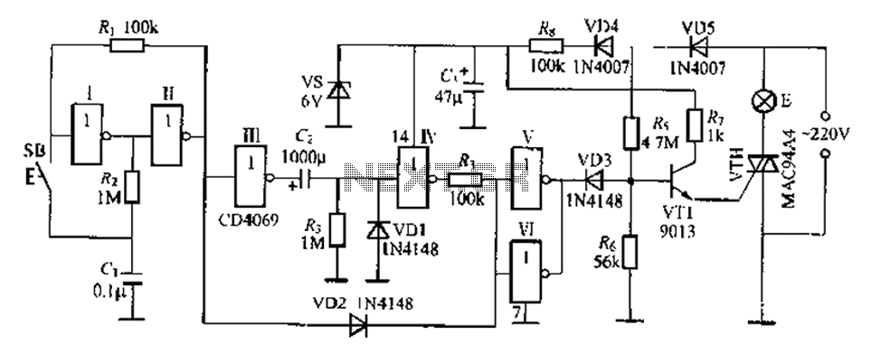
A delay lamp circuit is ideal for bedside tables, featuring a button (SB) that turns the light on and off. If the button is not pressed, the circuit maintains a delay before the light turns off. If the light...

Although analog and digital controllers may seem vastly different, their principles of operation are often quite similar. Therefore, popular analog tools like Spice can still be utilized to enhance common digital proportional-integral controllers through analysis, without the need for...

The AC adapter circuit is designed for portable digital products, converting low voltage DC into 220V AC. It features a circuit configuration for a switch power drill utilizing the oscillation IC LD7575 as a switch. This IC operates after...
The transmitter operating at 2 meters (144 MHz) was primarily designed for use by radio amateurs as a radio beacon. It generates a high-quality signal suitable for this purpose. The 2-meter transmitter circuit typically includes several key components to ensure...
This discussion continues from the audio tone control topic, which introduced both passive and active tone controls. The follow-up topics may include a 2-Band Active Tone Control or a 3-Band Active Tone Control. An audio equalizer is utilized to...
This device monitors sounds in a home or office when a telephone is called from a remote location. The described device functions as an audio monitoring system that activates upon receiving a telephone call. The core of this system typically...