
Solar Cell Voltage Regulator

The circuit is designed to monitor voltage levels in a solar power supply system, providing visual feedback through two LEDs that indicate whether the voltage is within acceptable limits. The use of a low-dropout voltage regulator allows for efficient operation, ensuring that the circuit can function properly even when the input voltage from the solar cells is slightly lower than the nominal 5V. The choice of transistors, BC557B and BC547B, ensures that the circuit can switch appropriately based on the voltage levels detected.
The configuration of resistors in the voltage dividers is critical for setting the thresholds at which the LEDs activate. Adjustments may be necessary to accommodate variations in transistor gain and the desired response to voltage changes. The circuit operates effectively within a range of input voltages, making it versatile for different solar cell configurations.
In terms of functionality, the two LEDs serve distinct purposes: LED D2 indicates a healthy voltage level, while LED D1 serves as a warning signal for low voltage conditions. The dim illumination of both LEDs in the intermediate voltage range provides a visual indication of uncertainty, which can be useful for users monitoring the system.
For enhanced alerting capabilities, integrating a buzzer or similar alerting device across LED D1 can provide an audible warning when voltage drops below the operational threshold, further ensuring that users are informed of critical voltage conditions. The overall design is efficient, with low power consumption, making it suitable for battery-powered applications where energy conservation is essential.
This comparator circuit is a practical solution for applications involving solar power, allowing for real-time monitoring of voltage levels and providing essential feedback to users.This device is designed to be a simple, inexpensive comparator`, intended for use in a solar cell power supply setup where a quick too low` or just right` voltage indicator is needed. The circuit consists only of one 5V regulator, two transistors, two LEDs, five resistors, two capacitors, and one small battery.
Although a 4-V battery is indicated, 4. 5 V (3 alkalines in series) or 3. 6 V (3 NiCd cells in series) will also work. The specifications of voltage regulator IC1 are mainly determined by the size and number of the solar cells and the current pull of the equipment connected to the output. Here the low-drop 4805 is suggested but other regulators may work equally well as long as you observe the output voltage of the solar cells.
Transistors T1 and T2 are complementary types i. e. one each of the pnp and npn variety. Although the ubiquitous BC557B (pnp) and BC547B (npn) are indicated, any small-signal equivalents out of the junk box will probably do. The values of voltage dividers R1/R6 and R3/R4 may need to be adjusted according to the type of transistor and its gain, or according to the desired voltage thresholds.
Using the resistor values shown in the schematic, LED D2 turns on fully when the voltage is just above 5 volts. LED D1 turns on when the voltage drops below 4. 2 volts or so. Between those two thresholds, there is a sort of no man`s land where both LEDs are on dimly. A buzzer or other warning device could be connected across the terminals of LED D1 to give a more substantial warning if the voltage drops below operating limits.
The current consumption of the circuit is about 20 mA at 5 V, and it decreases with the voltage supplied by the solar cells. 🔗 External reference
Related Circuits
These power supply circuits generate 500 volts, but they can be modified to supply several hundred to nearly 1000 volts by changing the zener diodes. These circuits produce high voltages and can cause dangerous shocks. Caution is advised; these...
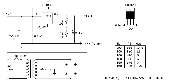
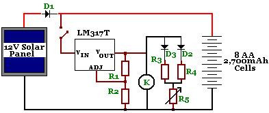
The LM317T is an adjustable three-terminal positive voltage regulator that can supply over 1.5 amps with an output voltage range of 1.25 to 37 volts. It features built-in current limiting and thermal shutdown, making it highly reliable and resistant...
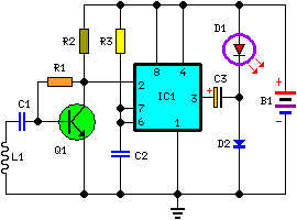
This circuit is designed to detect incoming calls on a cellular phone, even when the phone's ringer is turned off, by utilizing a flashing LED. The device should be positioned a few centimeters away from the cellular phone, allowing...
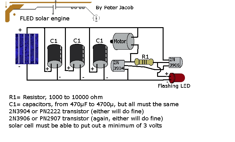
This document outlines the construction of a trimet. The required components include three capacitors, a 2N3904 transistor, a 2N3906 transistor, a resistor with a value between 1k to 10k ohms, and a solar cell with a minimum voltage of...
The circuit is designed to power a CCTV camera, provide lighting inside a nestbox, and charge batteries using a photovoltaic (PV) solar panel. It includes a circuit diagram for a solar-powered wireless CCTV camera with battery backup. D1 is...
This circuit enables a microprocessor system to measure its own battery voltage. A Texas Instruments TI43 precision shunt regulator functions as a precise reference and integrator/amplifier, measuring its own supply through voltage-dependent charge and discharge time intervals. It is...