
Battery-Voltage Measuring Regulator
The circuit design incorporates a Texas Instruments TI43 precision shunt regulator, which is known for its stability and accuracy in voltage regulation applications. The TI43 operates by maintaining a constant output voltage, which serves as a reference point for measuring the battery voltage.
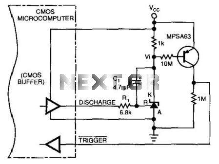
To facilitate the measurement process, the circuit includes an integrator/amplifier configuration that captures the voltage across the battery. The voltage-dependent charge and discharge time intervals are critical; they allow the circuit to respond accurately to changes in battery voltage. This is achieved by monitoring the time taken for the capacitor in the integrator circuit to charge and discharge, which varies based on the battery voltage level.
The output from the integrator/amplifier is then fed into the microprocessor, which requires a software routine to interpret the voltage levels. This routine should include algorithms to calculate the battery voltage based on the measured time intervals and the known characteristics of the TI43 shunt regulator. The software will likely involve analog-to-digital conversion processes, ensuring that the microprocessor can read the voltage levels accurately and make decisions based on the battery's state.
In summary, this circuit not only measures the battery voltage effectively but also integrates seamlessly with the microprocessor system, requiring careful software development to ensure accurate readings and appropriate responses to varying battery conditions. This circuit allows a microprocessor system to measure its own battery voltage. A Texas Instrument TI43 1 precision shunt regulator acts as a precision reference and integrator/amplifier, measuring its own supply via voltage-dependent charge/discharge time intervals. Notice that you must write a short control and voltage calculation software routine for your system. 🔗 External reference
Related Circuits
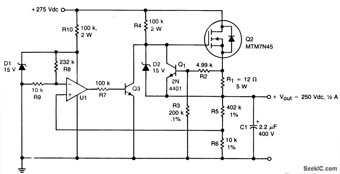
A TMOS MTM7N45 (Q2) functions as a series pass element in a linear high voltage supply that accepts +275 V unregulated input and produces a regulated output of 250 V, incorporating foldback current limiting. A 15 V zener diode,...
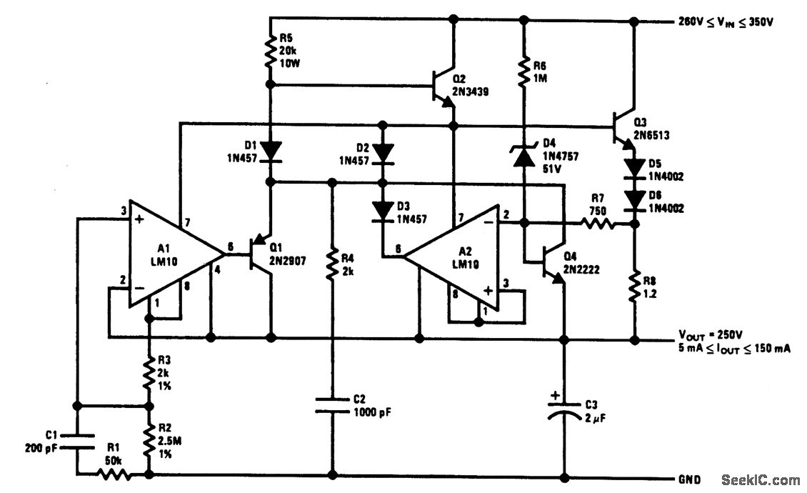
The output current is sensed across R8 and delivered to the current-limit amplifier through R7, where the foldback potential is developed by R6, with a threshold determined by D4. The specified values limit the peak power to below 20...
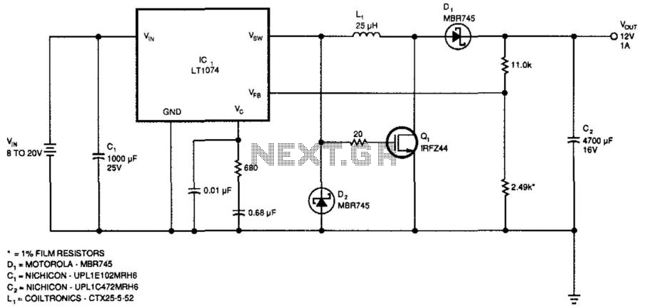
This regulator provides 12 V at 1 A output with an input voltage range of 8 to 20 V. The output voltage can be adjusted by changing the values of the resistors ll-kii and 2.49 kΩ to achieve 2.21...
The LM317 is an adjustable, positive 3-terminal voltage regulator capable of supplying 100 mA (for RA87U control) or 1.5 A (for Order Code UF27E and N61CA) across an output voltage range of 1.2 V to 37 V. These voltage...
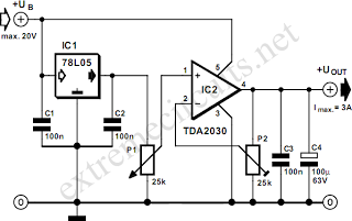
By combining a standard 78L05 voltage regulator with an integrated audio amplifier, specifically the TDA2030, it is possible to construct a simple yet effective adjustable voltage regulator. This regulator can output a voltage adjustable up to 20 V and...
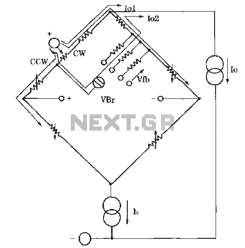
The circuit for zero and span adjustment consists of a feedback resistor network and a differential pressure sensing bridge measuring circuit. A constant current source, IO, represents the output current. The resistances of the four bridge arms are R1S,...