
Solar Charger Build

The described project utilizes solar cells configured in a parallel and series arrangement to enhance both voltage and current output for practical applications, specifically for charging USB devices. Each solar cell, identified by the code "PCB-60608B," is approximately 2.25 inches square and integrates into a larger assembly with capacitors and perf boards. The design incorporates 39 solar cells across 13 assemblies, allowing for a scalable approach to solar energy harvesting.
In the initial testing phase, the cells demonstrated a voltage output of approximately 3 volts under artificial lighting conditions, which prompted the arrangement of three cells in series to achieve a near 9-volt output. This configuration is essential for applications requiring higher voltage levels, while the measured short-circuit current of around 10 mA indicates the cells' performance under less than optimal light conditions. The expectation is that exposure to direct sunlight will yield significantly improved performance metrics.
To construct an efficient solar panel, the design employed eight solar cells wired in series pairs, resulting in four distinct 6-volt panels. These panels were then connected in parallel, facilitating an increase in the overall current output, which is crucial for charging applications. The integration of a 7805 linear voltage regulator serves to convert the 6-volt output to a stable 5 volts suitable for USB charging. However, this regulator's inherent inefficiency, characterized by energy loss as heat, poses a limitation for solar applications where energy conservation is paramount.
To enhance overall efficiency, the implementation of a DC/DC converter is proposed. This device functions by stepping down voltage while increasing current, thereby optimizing power delivery to the load. The fundamental principle of power conservation (power = voltage × current) is leveraged in this context, with the DC/DC converter designed to minimize losses and improve the charging efficacy of the solar panel system. This comprehensive approach ensures that the solar panel not only meets the voltage requirements for USB devices but also maximizes current output, thereby enhancing the overall performance of the solar energy harvesting system.Whatever past project these were used in obviously required three cells to be wired in parallel with a rather large (4700 uF) capacitor on a perf board. There were 13 of these board assemblies, for a total of 39 solar cells and 13 capacitors (not to mention the 13 perf boards themselves).
The cells themselves are about 2. 25 inches square, and have `PCB-60608B` written on the back of them. Strangely, even though each solar panel was labeled with the same number, there was quite a variety of differing panel styles. Anyways, I couldn`t find much on the `PCB-60608B` solar cells, but I did find what appears to be a schematic of the solar-powered accent lights these panels were made for.
I started doing some tests with the cells to see what sort of power they could produce. They actually did pretty well, even under a simple table lamp. Anxious to try them out on the sun, but with the sun long past the horizon, I had to make do with halogen lights. It appeared that one cell was able to put out around 3 volts under the light of my desk lamp. Good! I wired three of them together in series and sure enough, I got an output near 9 volts. It was exciting to verify that the cells were in working order, and indeed put out a relatively high voltage.
I measured the short-circuit current of one cell under the desk lamp, and (as I expected) it was quite low-around 10 mA. Surely, under sunlight, there would be a higher power output. Also, I`m able to wire the cells in parallel to increase the maximum current output of the solar panel-voltages add when cells are in series, and currents add when they are in parallel.
I went about constructing such a panel. I wired eight cells in series pairs to get four 6 volt panels. Then, I wired these in parallel so that I got some sort of usable current out of the 8-cell solar panel. I figured I would want to charge USB devices, so I dug up a 7805 5V linear voltage regulator to bring the 6 volt output down to 5 volts.
After hooking up an old USB port, I was able to test the charging capabilities of my newly-built solar panel. It worked! My iPod successfully went into "charge mode" upon connecting it to the panel and turning on the desklamp.
Once I understood the cells` output, I made a nice 16-cell panel for charging my devices. They are wired in pairs so that the output is around 6 volts, and with 8 of these pairs wired in parallel, the current output should be acceptable. If the current output of a solar panel is too low, the device may charge very slowly or even lose charge.
If the charger is supplying less power than the cell phone uses by simply being on, then it will lose power, even though it may tell you that it is charging. Solar cells are quite inefficient at converting light into electricity. That meant I wanted to be as efficient as possible when charging my USB devices. Unfortunately, the 7805 linear voltage regulator (as pictured above) is very inefficient. The voltage regulator takes a variable voltage input (above 5V) and outputs a relatively steady 5 volts.
It works by simply burning off the extra energy as heat, which doesn`t make much sense for a solar charger. So, I looked into a DC/DC converter, which is really just a transformer. It takes a higher voltage input, and puts out power that is at a lower voltage, but carries more current.
Ideally power (power = voltage*current) would be conserved, but in reality, DC/DC converters are 🔗 External reference
Related Circuits
It is difficult to envision modern society without batteries. A quick inventory of gadgets in any household reveals a surprising number of battery-operated devices. Most of these devices utilize penlight batteries, and environmentally conscious users are likely opting for...
Savings on electricity bills can be achieved by utilizing alternative power sources. The photovoltaic module or solar panel described here has a power output of 5 watts, providing 16.5V under full sunlight conditions, with a current delivery of 300-350...
This is the simplest and most affordable solar battery charger that a hobbyist can create. It has some drawbacks compared to other similar controls, but offers unique advantages. The solar battery charger circuit is designed to harness solar energy to...
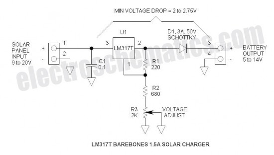
Charger for all battery types power supply. This lithium battery charger circuit is dedicated to charging lithium batteries. It uses two chips: the voltage regulator LM317T and ICL7665, which warns microprocessors of overvoltage and undervoltage conditions. Charging is completed...
This example implements a clock using 36 lines of Perl code. It displays the time and date, with a small icon called "heartbeat" in the upper right corner. The "heartbeat" icon, added by the LCDd server, blinks intermittently to...
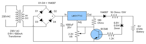
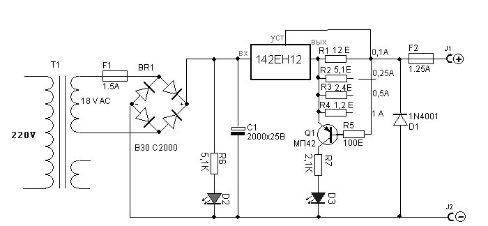
The battery charger circuit is designed to charge 6V 4.5 AH lead-acid batteries. The schematic is straightforward and utilizes only a few components. The IC LM317T serves as the core component of the circuit. It features an automatic charging...