
NiMH Charger For Up To Six Cells
The charger circuit for NiMH batteries using the MAX712 IC is designed to ensure safe and efficient charging. The MAX712 integrates several functions necessary for managing the charging process, including monitoring voltage, current, and temperature. The use of a transistor (T1) allows the circuit to regulate the charging current effectively, while resistor R1 serves as a current sensing element, providing feedback to the MAX712 for accurate control.
The configuration of the PGM inputs allows for flexible setting of the charger according to the specific battery configuration being charged. The presence of dongles for adjusting the number of cells and maximum charging time simplifies the user experience, enabling quick adaptations for different battery types and capacities.
Thermal management is also a consideration in this design, as excessive heat can damage batteries and reduce their lifespan. The potential need for a heatsink on T1 highlights the importance of thermal dissipation in high-current applications.
Overall, this circuit represents a practical solution for household battery charging needs, particularly for users transitioning from older NiCd technology to more efficient NiMH batteries, reflecting contemporary environmental considerations and user convenience in battery management.It is impossible to imagine present day society without any batteries. Count the number of gadgets in your house that are powered from batteries, you will be stunned by the number of batteries you will find. The majority of these devices use penlight batteries and if you`re a little environmentally conscious you will be using rechargeable batterie
s. A few years ago these batteries were invariably NiCd types. However, these batteries suffer from a relatively high rate of self-discharge and from the so-called memory-effect. It is now more common to use NiMH batteries. The advantage is that these batteries do not suffer from the memory-effect and generally also have a much higher capacity, so that they last longer before they have to be recharged again.
From the above you can conclude that every household these days needs, or could use, a battery charger. A good charger needs to keep an eye on several things to ensure that the batteries are charged properly.
For one, the charger has to make sure that the voltage per cell is not too high. It also needs to check the charging curve to determine when the battery is fully charged. If the charging process is taking too long, this is an indication that something is wrong and the charger must stop charging. Sometimes it is also useful to monitor the temperature of the cells to ensure that they do not get too hot.
The circuit presented here is intended for charging NiMH batteries. The MAX712 IC used here contains all the necessary functionality to make sure that this happens in a controlled manner. Figure 1 shows the schematic of the charger. The heart of the circuit is easily recognized: everything is arranged around IC1, a MAX712 from Maxim.
This IC is available in a standard DIP package, which is convenient for the hobbyist because it can be directly fitted on standard though-hole prototyping board. IC1 uses T1 to regulate the current in the battery. R1 is used by IC1 to measure the current. While charging, IC1 attempts to maintain a constant voltage, equal to 250 mV, across R1. By adjusting the value of R1 the charging current can be set. The value of R1 can be calculated using the formula below: R1 = 250 mV / I charge For a charging current of 1 A, the value of R1 has to be 250 mV / 1 A = 0.
25 . The power dissipated by R1 equals U G— I = 0. 25 G— 1= 250 mW. A 0. 5-watt resistor will therefore suffice for R1. Transistor T1 may need a small heatsink depending on the charging current and supply voltage. IC1 needs a small amount of user input regarding the maximum charging time and the number of cells in the battery to be charged. IC1 has four inputs, PGM0 to PGM3, for this purpose. These are not ordinary digital inputs (which recognise only 2 states) but special inputs that recognise 4 different states, namely V+, Vref, BATT or not connected.
To make this a little bit more user friendly, we`ve brought out the necessary connections to 2 connectors (K3 and K4). A number of dongles have been made (Figure 2) that can be plugged into these connectors and set the number of cells and the maximum charging time.
When determining the maximum charging time we have to take into account the charging current and the capacity of the cells that are connected. The charging time can be calculated with the formula: Tcharge = Ccell / I charge G— 1. 2 where Ccell is the capacity in Ah (e. g. , 1200 mAh = 1. 2 Ah). After the nominal charging time has been calculated, we can use the first dongle that has a value that is equal or greater than the calculated charging time.
For example, if we calculated a maximum charging time of 38 minutes, we have to select the dongle for 45 minutes. When IC1 is replaced by a MAX713, the charger becomes suitable for charging NiCd batteries (but not suitable for NiMH batteries any more!).
The only difference between these two ICs is the value of the detection point at which the cell(s) are considered to be completely charged. The ICs are otherwise identical with regard to pin-out, method of adjustment, etc. To make it easy to swap between the ICs, we recommend an IC-socket for IC1. 🔗 External reference
Related Circuits
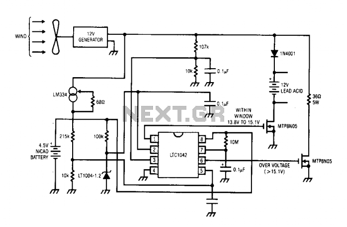
The DC motor operates as a generator, with the voltage output being directly proportional to its RPM. The LTC1042 monitors this voltage output and provides various control functions. When the generator voltage output falls below 13.8 V, the control...
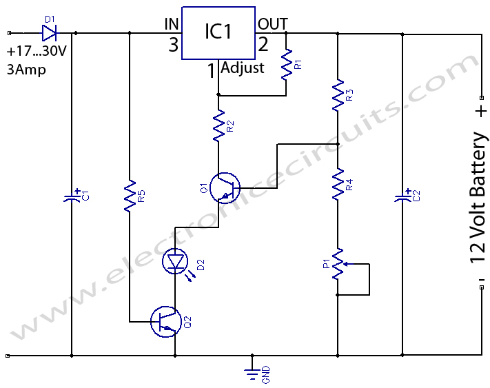
12 Volts Lead Acid Battery Charger Circuit. Apart from serving as a standard battery charger, this circuit is ideal for providing a constant charge to a 12-Volt lead-acid battery. This 12-Volt lead-acid battery charger circuit is designed to efficiently charge...
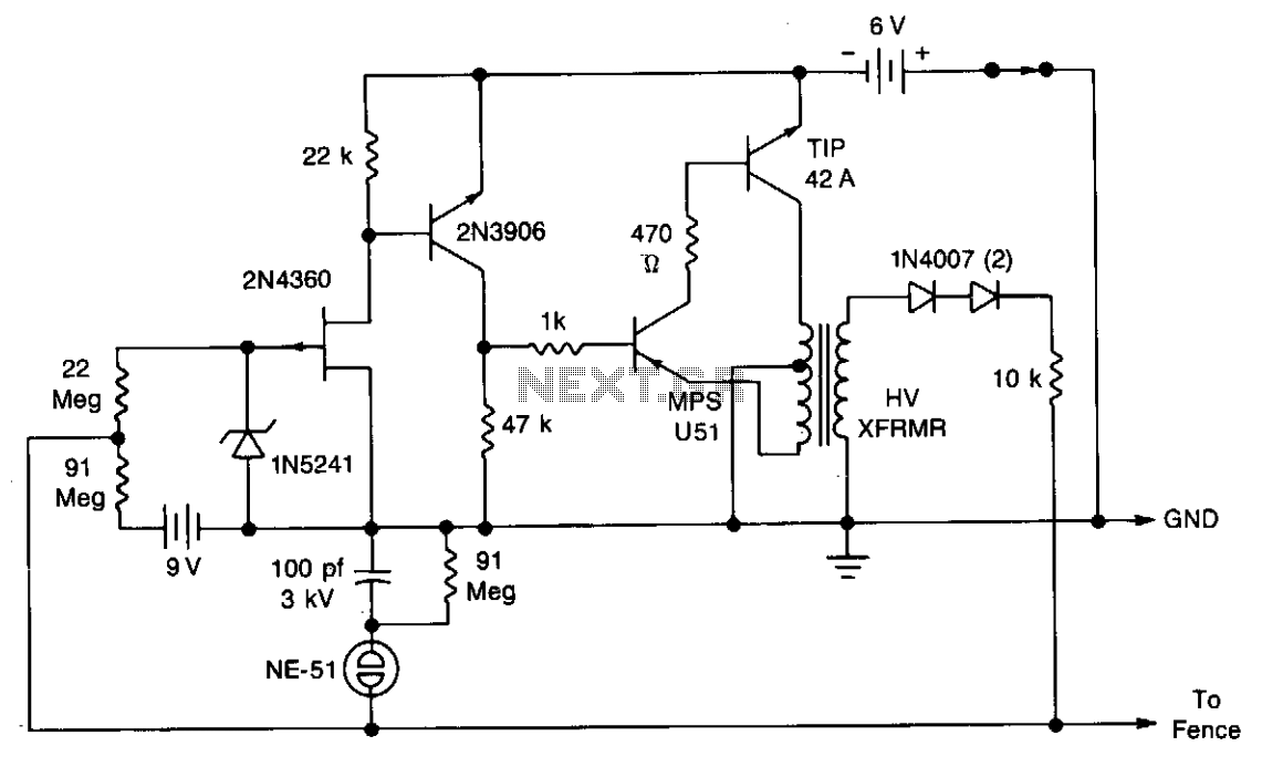
A touch-sensing circuit maintains the high-voltage generator in an off state until contact is made with the fence wire. When something touches the fence sensing circuit wire, it activates the high-voltage generator, which delivers a series of 500-microsecond pulses...
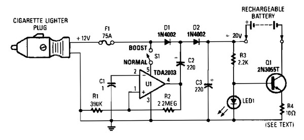
V1 creates a square wave oscillator, while D1 and D2 couple this square wave to a 12-V battery, raising the voltage to over 20 VDC. If this elevated voltage is not required, S1 can remain open. Q1 functions as...
This circuit is capable of automatically charging 6V and 12V batteries quickly and accurately. A key factor in the successful operation of the circuit is the use of a high-quality transformer (T1) that features excellent insulation and short-circuit resistance. The...
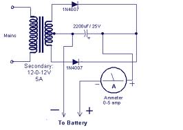
This design presents a circuit diagram for a straightforward battery charger capable of charging various types of 12V rechargeable batteries, including car batteries. The ammeter reading will indicate zero when the battery is fully charged. It is essential to...