
Solar Charger Monitor Circuit
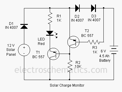
The described add-on circuit serves as a visual indicator for the charging status of a battery connected to a solar charger. The primary function is to illuminate a red LED, which provides a clear and immediate indication of the battery's charging state.
The circuit typically consists of a voltage divider, a transistor, and the LED. The voltage divider is connected across the battery terminals to monitor the voltage level. When the solar charger is operational and the battery is receiving charge, the voltage across the battery will rise above a predetermined threshold. This change in voltage is detected by the transistor, which acts as a switch.
When the transistor is activated, it allows current to flow through the red LED, causing it to light up. The choice of a red LED is significant, as red is often associated with alertness, making it an effective choice for indicating charging status.
In addition to the LED and transistor, the circuit may also include a resistor to limit the current through the LED, ensuring it operates within safe parameters. The design should also consider the power rating of the components to withstand the maximum expected current from the solar charger.
Overall, this simple yet effective circuit enhances the functionality of a solar charger by providing a straightforward visual cue regarding the battery's charging condition, thereby aiding users in monitoring the solar charging process.This add on circuit can be attached to the solar charger to see whether the battery is charging or not. It lights a Red LED to indicate that the battery is.. 🔗 External reference
Related Circuits
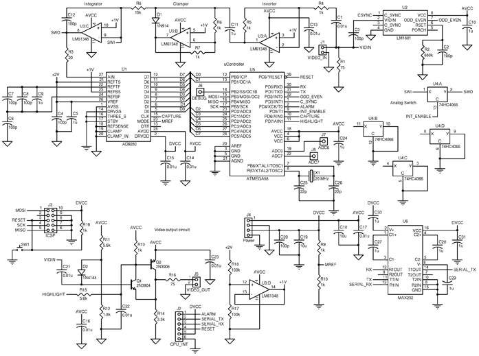
The circuit includes an ATmega88 as the main controller, an AD9280 ADC, an LM6134 high-speed quad op-amp, an LM1881 video sync separator, a 74HC4066 as a simple analog switch, and an RS-232 level converter. The LM1881 video sync separator...
The I2C serial bus is a widely used two-wire bus for small-area networks. The I2C Clock and Data lines feature open collector (or drain) outputs for each device on the network, requiring only a single pull-up resistor. This architecture...
The applet shows a simulation of Chua's circuit, plotting the voltage measured across C1 against the voltage measured across C2. This corresponds to the display on an X-Y oscilloscope with probes connected across these capacitors. The initial values of...
This active antenna schematic can be used to frequency range from 10 KHz to 100 MHz. The length of the Antenna can be between 0.5 to 1 meter long. The power consumption is 20-30mA. More: Use the shortest possible...
Direct measurement circuit for soil content, assessing various parameters such as moisture, salinity, nitrogen, and pH to enhance soil quality for diverse agricultural crops. This electronic measuring circuit facilitates rapid and accurate testing of soil conditions and informs fertilization...
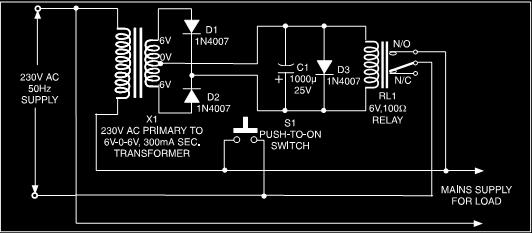
This is a low-cost protection circuit designed to safeguard electrically operated home appliances, such as TVs, DVD players, refrigerators, and other devices, during sudden power outages and the subsequent restoration of mains supply. Appliances like refrigerators and air conditioners...