
lm1881 video sync for tv and lcd monitor separator
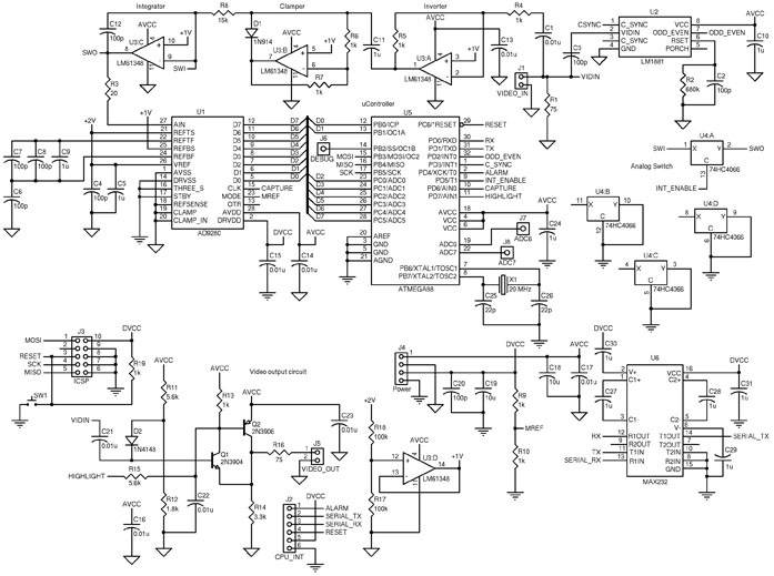
The circuit design integrates several key components to facilitate video signal processing and synchronization. The ATmega88 microcontroller serves as the core processing unit, managing data acquisition and control signals. The AD9280 analog-to-digital converter (ADC) is employed for converting analog video signals into digital format, enabling further processing by the microcontroller.
The LM6134 high-speed quad operational amplifier is utilized for signal amplification and buffering, ensuring that the video signals maintain integrity and minimal distortion during processing. The LM1881 video sync separator plays a crucial role in extracting synchronization information from composite video signals, which is essential for maintaining proper timing in video applications. It operates effectively with various video standards, including NTSC, PAL, and SECAM, accommodating a range of signal amplitudes.
The 74HC4066 analog switch allows for the routing of signals within the circuit, enabling flexible signal management without introducing significant noise or distortion. Additionally, the RS-232 level converter facilitates communication between the microcontroller and external devices, ensuring compatibility with standard serial communication protocols.
The RGB signal connections are designed to interface with various video sources, with specific grounding and signal specifications for each color channel (Red, Green, and Blue), as well as composite video inputs and outputs. Each signal line is characterized by a specified voltage level and impedance (75 ohms), which is essential for maintaining signal quality and preventing reflections in high-frequency applications.
Overall, this circuit is well-suited for applications requiring video signal processing, synchronization, and conversion, providing a robust platform for further development in video electronics.The chips include an ATmega88 as the main controller, an AD9280 ADC, an LM6134 high-speed quad op-amp, an LM1881 video sync separator, a 74HC4066 as a simple analog switch, and an RS-232-level converter. LM1881 Video sync separator extracts timing information including composite and vertical sync, burst/back porch timing, and odd/even field inform
ation from standard negative going sync NTSC, PAL* and SECAM video signals with amplitude from 0. 5V to 2V p-p. 5 RGB Blue Ground 7 RGB Blue Signal (0. 7Vpp 75 ohm) 9 RGB Green Ground 11 RGB Green Signal (0. 7Vpp 75 ohm) 13 RGB Red Ground 15 RGB Red Signal (1Vpp 75 ohm) 17 Composite Video Ground 19 Composite Video Out (1Vpp 75 ohm) 20 Composite Video In (1Vpp 75 ohm) 🔗 External reference
Related Circuits
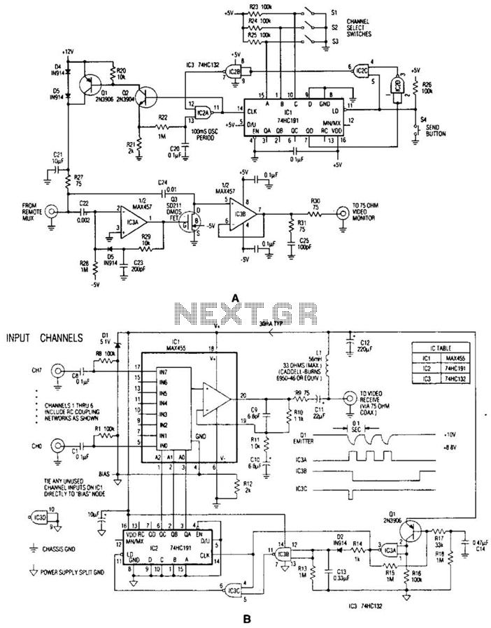
In the video system illustrated in Figures A and R, a single coaxial cable transmits power to a remote location, selects one of eight video channels, and returns the selected signal. This system can choose from several remote surveillance...
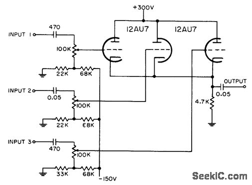
Each grid is biased to cutoff, allowing the mixer to accept only positive-polarity pulses with sufficient amplitude to overcome this bias. -NBS, "Handbook Preferred Circuits Navy Aeronautical Electronic Equipment," Vol. 1, Electron Tube Circuits, 1963, p N4-2. In a typical...
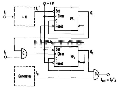
This circuit generates an output frequency that is linearly proportional to the ratio of two input frequencies. Each pulse of the bias frequency will open a switch for a period equal to half of the second input frequency, allowing...
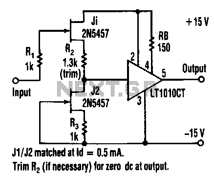
This buffer amplifier's overall harmonic distortion is low at 0.01% or less at a 3-V RMS output into a 500-ohm load without overall feedback. The LT1010CT features a slew rate of 100 V/µs, a video bandwidth of 20 MHz,...
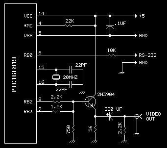
Want to add video to your next project? This device uses a PIC16F819 and not much else. Getting 20 characters to a line is possible by using the SPI port to generate video. Neat trick, eh? The character set...
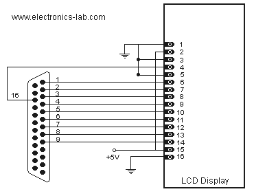
Connecting a LCD display to your personal computer is an easy job. Displaying data from your PC to a LCD can be proven very exciting, so give it a try and build your own today! In this article, we...