
Solar charging a Nokia N95

The initial step involved understanding the charging mechanism of the phone. Given the complexity of power management and the expense of the devices, caution was exercised to avoid damaging the phones during testing. Fortunately, this stage proved more manageable than anticipated. The factory charger was identified as a standard 5V AC adapter, outputting approximately 7.2 volts DC at 880 milliamps. The next phase required determining the minimum and maximum power levels the N95 could accept at the charge port while still functioning correctly. The approach involved cutting the tip off the power adapter, testing the wire polarity, and connecting it to a variable power supply to observe the phone's response as voltage was adjusted.
The first hurdle arose when attempting to strip the wires from the newly cut adapter. The N95 charger utilized a flat cable, making traditional wire strippers ineffective. A method was developed to split the wire in half using an exacto knife, creating two separate wires that could be stripped with standard tools. Inside the flat cable, two conductors were discovered: one bare and one coated in red enamel. Initially, the red wire was identified as ground; however, it was later realized that the color mapping of the wires to the power sources inside the charger was arbitrary. Once the wires were accessed and polarity confirmed, it was expected that connecting to the bench power supply would be straightforward. However, even with the bench supply set to 7.5 volts and current limiting at 880 milliamps, the phone did not respond with the expected charging animation.
On a hunch, a resistor was introduced between the charger input and the bench output, which unexpectedly allowed the phone to charge, despite the bench supply already having current limiting features. This success indicated that the phone could charge with voltages ranging from approximately 4.1 to 10.5 volts DC. With this information, the next step was to identify solar panels that would meet these voltage requirements, fit within the budget, and have an appealing aesthetic for bike integration. A large solar cell was selected, capable of producing over 8 volts and 300 milliamps in direct sunlight, outperforming competitors in its price range. The panels were also visually appealing and came pre-sealed with long leads, which added to their attractiveness. Subsequent water tests confirmed their resistance to moisture, further solidifying the decision.
A single panel was ordered for testing, with the expectation of needing to construct an intermediary circuit for charging. However, during a sunny day on the roof, it was discovered that the phone charged directly from the solar panel, exceeding initial expectations. Further experiments revealed that the solar panel could charge the phone even in low light conditions and indoors under incandescent bulbs. This promising outcome led to inquiries regarding the charging duration of a depleted N95 on a sunny day using a single solar panel.
In conclusion, the integration of solar power into the Yahoo Purple Pedals project demonstrates a successful approach to off-grid energy solutions for electric bicycles, highlighting the importance of thorough testing and innovative problem-solving in electronics engineering. The project not only emphasizes the feasibility of renewable energy sources in everyday applications but also showcases the potential for sustainable technology in enhancing user experience and convenience.One of the coolest parts of working on the Yahoo Purple Pedals project was figuring out how we could get the bikes as far off the grid as possible. Once we decided on using the N95 as the brain for the bikes, we had to figure out how much juice it takes to run the code, how often the code was going to run, and how we could prevent our users fromhaving to plug-in the bike everyday like a cell phone.
After thinking through and testing out a few different ideas, we settled on solar power as the simple, inexpensive, green, and aesthetically pleasing solution. In the following walk-through I am going to explain the design process and how we got from the idea of using solar to creating a solar replenishing backup power system that can run off the grid for weeks on end.
The first step was figuring out how the phone charged. Power can be a tricky business and the phones weren`t cheap so we didn`t want to accidentally fry one in testing. Luckily, this step turned out to be a lot easier than we expected. The factory charger was a regular 5V AC adapter which output about 7. 2 volts DC at 880 milliamps. The next step was to figure out the minimum and the maximum power levels the N95 could take in at the charge port and still charge correctly.
Our idea was to cut the tip off the power adapter, test the polarity of the wires inside, mate it to a variable power supply, and see what happened to the N95 as we cranked up and down the juice. The first challenge came when we went to strip the wires on our newly cut adapter wire. The N95 charger uses a flat cable to connect from the tip to the body, which means you can`t use regular wire strippers to get at the copper inside.
We devised a technique of splitting the wire in half with an exacto knife to create two independent wires which were then possible to strip with regular tools. We discovered that inside the flat cable are two conductors, one bare and one coated in red enamel. On the first hacked adapter the red wire was ground, but as we later found out it was completely random which wire color was mapped to which power source inside the charger.
Once we got at the wire and got our polarity figured out we figured it would be easy enough to just clip onto the bench supply and start testing. Wrong. Even with the bench supply set at 7. 5 volts and current limiting set to 880 milliamps the phone refused to make its little beep and display the charging animation.
On a hunch we tried putting a resistor between the charger input and the bench output, and somehow, even though the bench supply was supposedly already current limiting, for some reason this worked. Hurray! We got the phone charging on anything from about 4. 1 to 10. 5 volts DC. Now that we knew the acceptable range for charging the phone we had to find some solar panels that would fall within this range, fall within our budget, and look cool on a bike.
We decided on the large solar cell available. it outputs over 8 volts and 300 milliamps in direct sunlight, beating all others that we found in its price class. To top it off they look cool and come all sealed and soldered up with long leads. Later water tests proved that they were water resistant which really sealed the deal for us. We ordered one to try it out, expecting that we would have to build a circuit between the panel and the phone to actually get it to charge.
With low expectations, we soldered the already hacked charger tip to the solar panel (double checking the polarity of course) and took a trip to the roof on a sunny day. We found, much to our surprise and delight, that the phone charged directly! Further tests showed that the solar panel would charge the phone in very low light conditions and even indoors under an incandescent bulb.
This was very exciting. Now we wanted to know how long it would take a single solar panel to charge a depleted N95 on a sunny day. To 🔗 External reference
Related Circuits
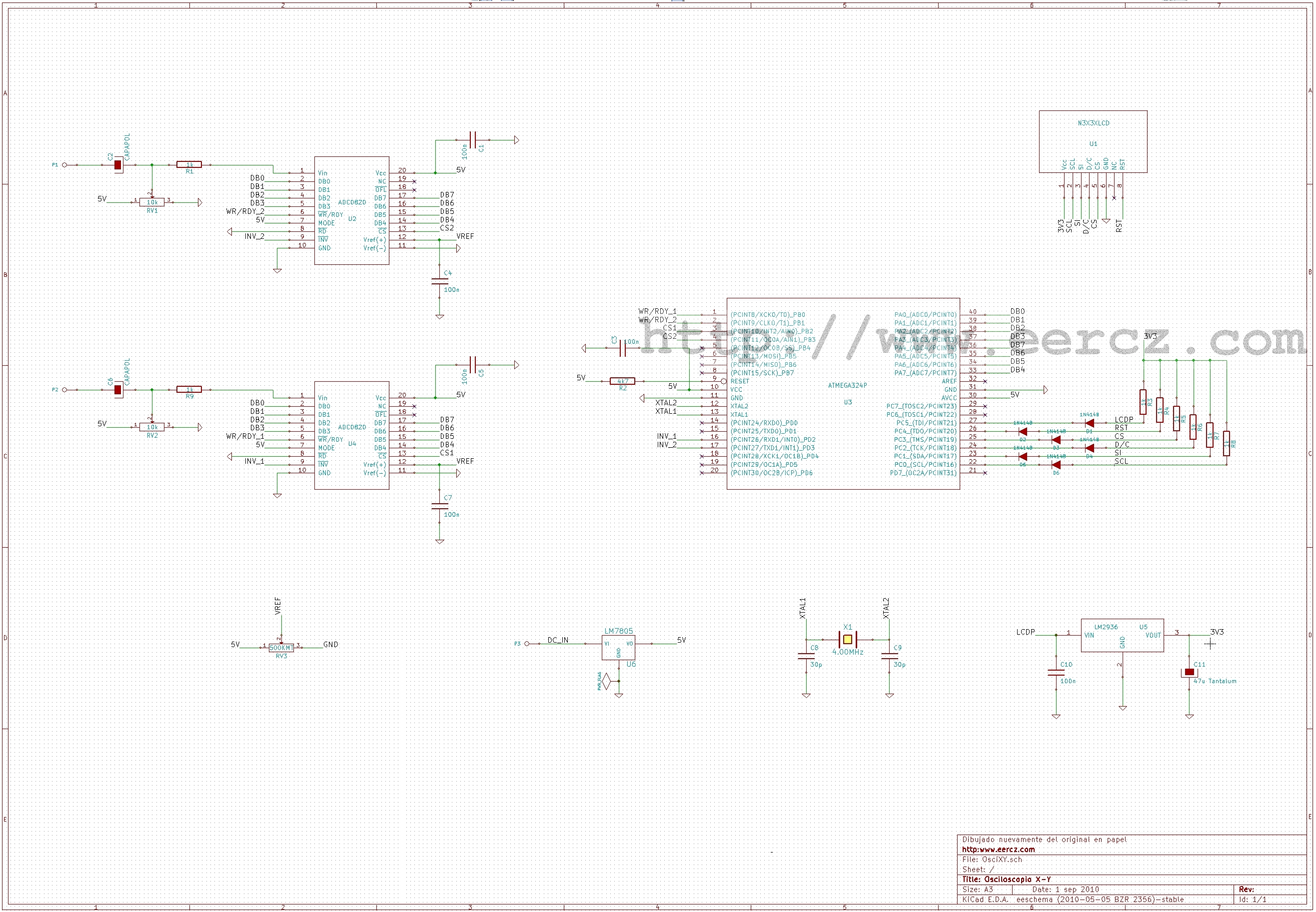
This is a straightforward X-Y oscilloscope design utilizing an ATmega324P microcontroller and two KAD0820 analog-to-digital converters (similar to National Semiconductor's ADC0820). The initial version of this oscilloscope was based on an AT90S4414, necessitating the use of external ADCs. Various...
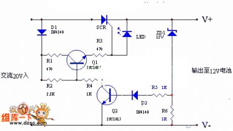
The circuit utilizes the positive half-cycle of an alternating current (AC) to charge a battery. It offers a rapid charging speed and has the potential to extend battery life. This charger is commonly used with standard motorcycles, demonstrating excellent...
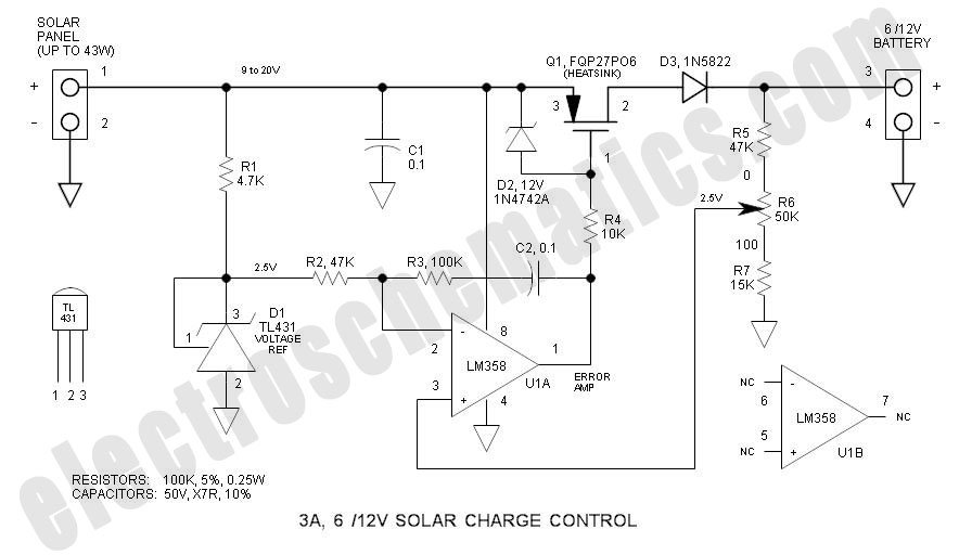
This solar charge controller integrates multiple features into a single design, including a 3A current rating, low dropout voltage (LDO), and a range of voltage adjustment capabilities. The solar charge controller is a critical component in solar energy systems, tasked...
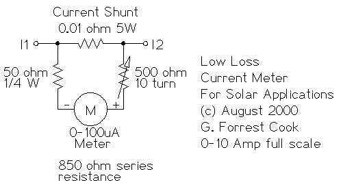
This circuit is used to measure the current from a solar panel. It has very low power loss for currents in the 0-10A range. It also works as a general purpose DC current meter. The circuit can be used...

This solar light bulb is designed to assist individuals residing in villages by offering an affordable alternative to harmful kerosene lamps. It aims to empower impoverished communities by replacing kerosene with clean, solar-powered lighting. The core component of this...
After a slight loss of field strength, magnets can be re-magnetized using a simple homemade porcelain filler. Locate scrap materials such as switches and contacts, as well as other models like CJ10-60 ~ 15. The circuit can operate at...