
One simple charging circuit b porcelain
In the context of re-magnetizing magnets using a homemade porcelain filler, it is essential to understand the components involved and the operational procedures. The Yamagata core serves as the primary magnetic material, which, when subjected to the appropriate voltage, can regain its magnetic properties. The circuit design should incorporate a fuse to protect against overcurrent conditions and a diode string to rectify the AC voltage, ensuring that the porcelain filler receives the necessary charge without damaging the circuit.
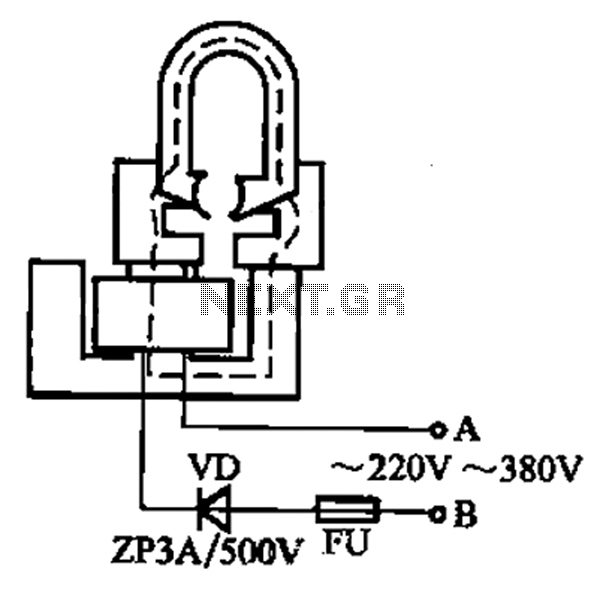
The magnetization process can be visually represented in two figures: Figure (a) for strip magnet magnetization and Figure (b) for soft iron magnetization using a U-shaped magnet. The connection to the AC power supply should be made with caution, as the high voltage can produce sparks. This indicates that the circuit is energized and functioning correctly. The specified waiting period of ten seconds is crucial, as it allows the magnetic field to stabilize before the next application of voltage.
After the magnetization process, the assembly should be left undisturbed for several hours. This resting period is vital for the magnetic properties to settle, enhancing the effectiveness of the re-magnetization. The final product will exhibit improved magnetic strength, enabling it to perform its intended function more effectively. Proper handling and safety measures during this process are paramount to prevent accidents and ensure successful re-magnetization.After some small loss of field magnets can be re-magnetized porcelain filled with homemade simple. Find a scrap of exchanges and contacts, and other models such as CJ10-60 ~ 15 0A (220V or 380V can), remove the word armature, only Yamagata core. In the coil circuit fuse and a diode string, they formed a charge porcelain, as 10-42 fold shown. Figure (a) applies to a strip magnet magnetization, FIG. (B) applies to soft iron by setting the U-shaped magnet. When magnetizing, with A, B both ends to touch 220V (nominal coil voltage of 220V) or 380V (rated coil voltage of 180V at) AC power supply (pay attention to safety), there are sparks when touched, just touch 1, 2 times. Wait ten seconds after the punch, then touch 1,2 times, magnetization ends. Then allowed to stand for several hours and then remove (this effect).
Related Circuits
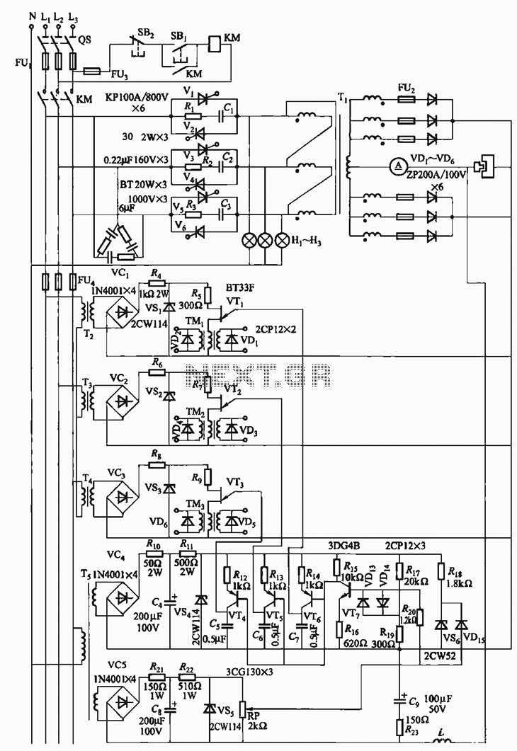
The 300A-18V three-phase thyristor power regulator circuit is designed for electrolysis applications. It can output a direct current of 3000A at an adjustable voltage of 18V, providing a power supply solution for various processing needs. The circuit comprises a...
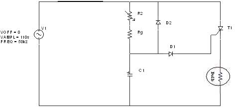
The diagram illustrates an R-C-Diode circuit that provides full half-cycle control (180 electrical degrees). During the positive half-cycle of the SCR anode voltage, the capacitor charges to the trigger point of the SCR, a process governed by the RC...
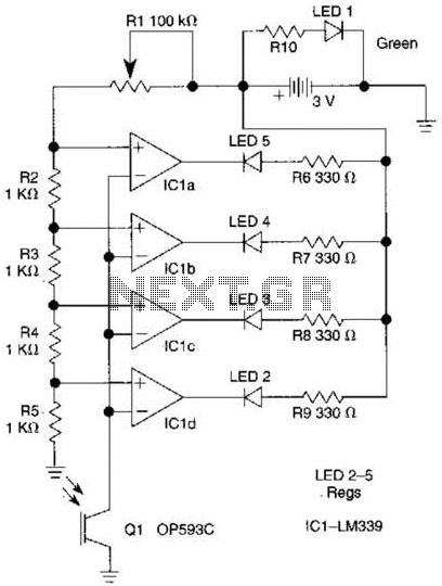
The outputs from the comparators will transition, in sequence, from high to low as the input voltage exceeds the reference voltage applied to each comparator. The output LEDs will activate sequentially as the voltage increases. The inverting inputs of...
An ultrasonic sound wave can be generated using an electronic circuit. This simple electronic circuit can generate an ultrasonic wave with a frequency range of 12 kHz and above. The electronic circuit designed for generating ultrasonic sound waves typically utilizes...
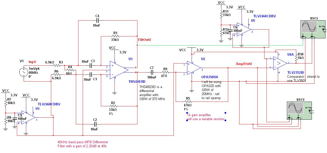
A circuit has been designed to detect the duration of an ultrasonic pulse as it travels a certain distance. The input signal is sourced from a 40 kHz ultrasonic receiver. The first stage consists of a 40 kHz band-pass...
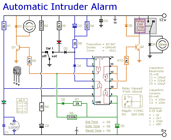
This is a simple single-zone home alarm system circuit. Its features include entry delays, a timed siren cut-off, and automatic exit. It is designed to be used with the usual types of normally-closed input devices such as foil tape,...
Warning: include(partials/cookie-banner.php): Failed to open stream: Permission denied in /var/www/html/nextgr/view-circuit.php on line 713
Warning: include(): Failed opening 'partials/cookie-banner.php' for inclusion (include_path='.:/usr/share/php') in /var/www/html/nextgr/view-circuit.php on line 713