
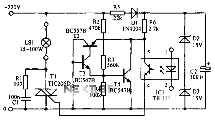
EMR4.0 application circuit

The EMR 4.0 circuit is designed to function optimally within specified voltage and current parameters. The power supply should be stable, with noise filtering implemented to ensure high fidelity during operation. The use of a 9V supply is ideal, as it balances performance and efficiency. The circuit's quiescent current of 11 mA indicates a relatively low power consumption, making it suitable for battery-operated applications.
To accommodate varying input signal levels, the EMR 4.0 is engineered to handle a maximum input of 1V. If the input signal falls below this threshold, it may lead to unwanted crossover distortion, particularly in the general assembly stage. This distortion can adversely affect the overall processing capabilities of the circuit, leading to a diminished dynamic range. Therefore, careful attention must be given to the input signal levels to ensure optimal circuit performance.
The output stage of the EMR 4.0 must incorporate a buffer amplifier to maintain signal integrity. This buffer amplifies the output without introducing additional noise, ensuring that the final output is clean and precise. Additionally, the integration of volume and tone controls prior to the output stage is crucial. These controls allow for adjustments that enhance the signal-to-noise ratio, thus further reducing distortion and improving audio quality.
In summary, the EMR 4.0 is a robust circuit that requires careful consideration of power supply, input levels, and output buffering to achieve high-performance audio processing. Proper implementation of these elements is essential for maximizing the circuit's potential and ensuring high-quality signal reproduction.EMR 4 0 with a single power supply (6V ~ 10V) power supply, power supply when 9V best. It requires better power filtering, noise lower opening the lc no signal input quiescent current of 11 deletion gas. RESEARCH contented 4-0 allow maximum input signal level is 1V, crossing over the General Assembly cause cut, too small will reduce the processing performance and reduces the dynamic range of the circuit gain o 1, which surround output must be connected to a certain gain buffer amplifier. Circuits should be connected with the volume and tone circuit before, in order to improve the signal to noise ratio and lower distortion o Figure 9-54 EMR 4.0 is the application circuit o
Related Circuits
A Darlington connection-type transistor is utilized for driving the coil. In this configuration, two stages of transistors are connected in series, resulting in a high current gain, where the "hfe" of the Darlington transistor is the product of the...

This design outlines a phone bug circuit. The wireless telephone line spy circuit is capable of transmitting phone conversations to a nearby FM radio. The circuit must be connected to a standard phone line. In the circuit, the first...
The circuit diagram illustrates the LED signal amplification. The LED signal amplification circuit is designed to enhance the output signal from an LED, allowing it to drive larger loads or to be interfaced with other electronic components effectively. The primary...
An RF probe is a circuit designed for testing equipment that converts high-frequency signals into DC voltage. This conversion facilitates the measurement of RF voltages for testing or adjusting transmitters, receivers, and modulators. The RF probe circuit outlined here...
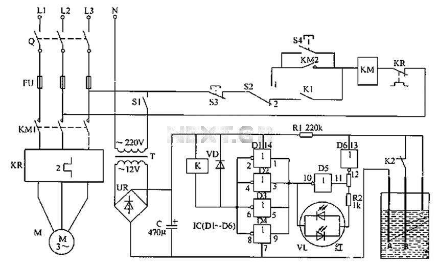
The liquid level automatic controller circuit consists of a power circuit, a control instruction level detection circuit, and a starter control circuit. The power circuit is formed by a power transformer, a rectifier bridge, and a filter capacitor. The...
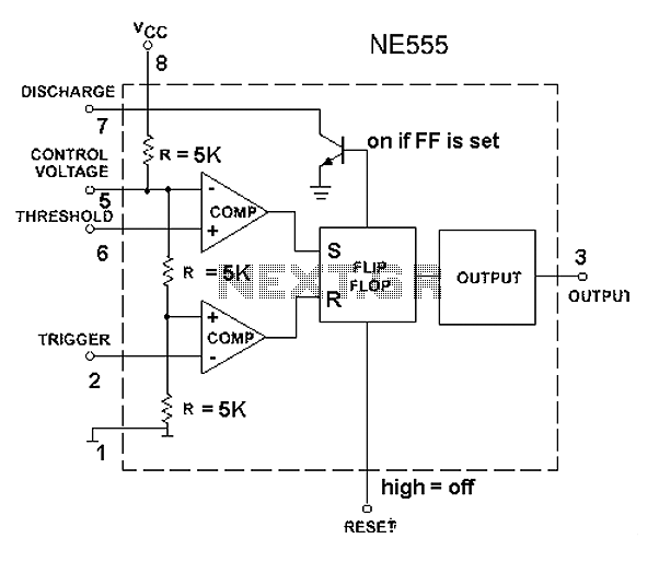
The 555 timer circuit, regardless of the manufacturer, has a consistent internal structure and performance. Various manufacturers produce different models of the 555 timer, including MC555, CA555, XR555, LM555, as well as domestic models like SL555, FX555, and 5G1555....