
Solar Mailbox project
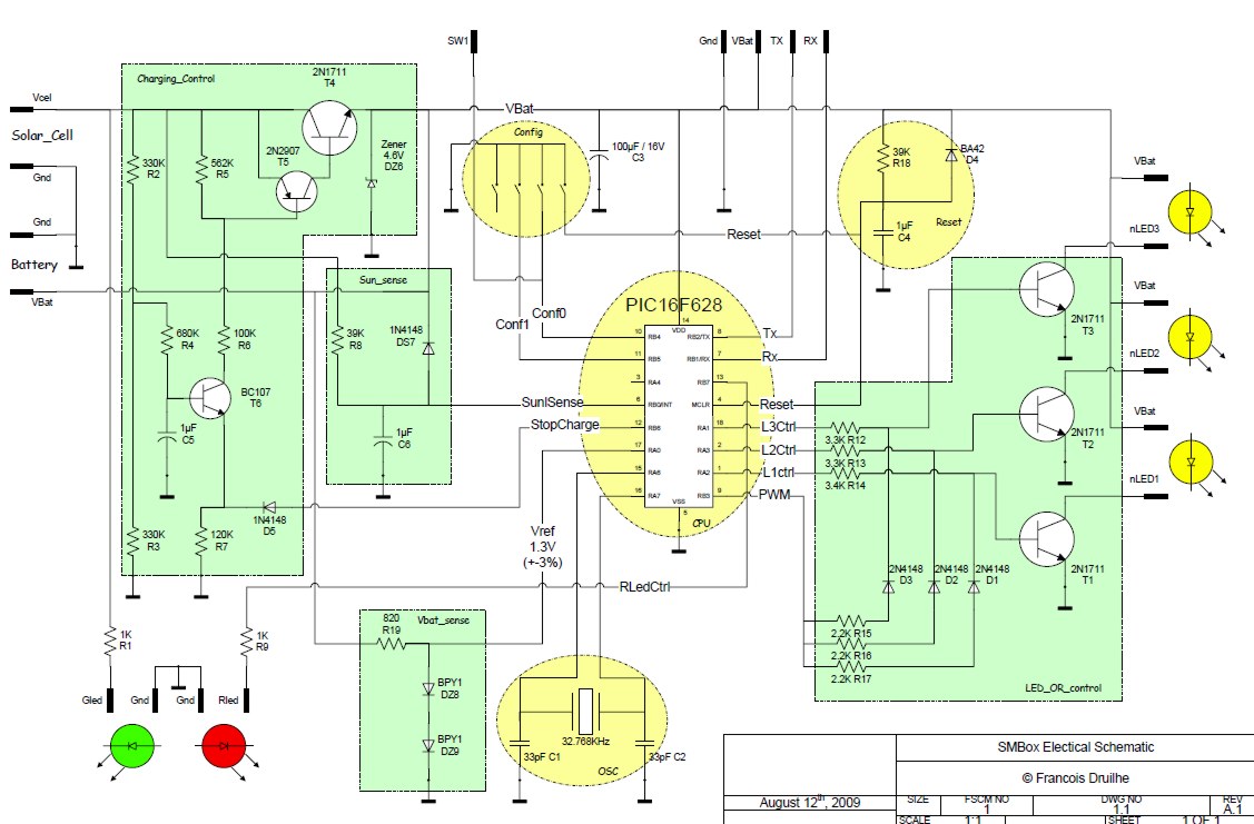
The schematic for this solar-powered mailbox includes several key components and configurations. The solar cell acts as the primary power source, charging the three AA NiMH batteries through the Sziklai pair, which effectively minimizes reverse current flow when sunlight is not available. The T5 (2N2907) and T4 (1N1711) transistors are configured to form this pair, ensuring high efficiency in transferring power from the solar cell to the batteries.
The charge control mechanism is facilitated by the D5 connection, which interfaces with the PIC microcontroller. When the PIC outputs a high signal, T6 is activated, allowing current to flow into the base of T5, thereby controlling the charging process. The Zener diode DZ6, rated at 4.6V, is crucial for protecting the battery from overcharging, which could lead to reduced battery life.
The display consists of three digits, each controlled by a separate 2N1711 transistor. Each digit is composed of approximately 20 white LEDs, arranged to form the house number. The control signal for the display is generated by combining a PWM signal, which maintains a constant light level, with a blinking signal produced by the PIC to create the desired display effect.
For sensing purposes, the Sun_Sense circuit employs a low-pass filter made from resistor R8 and capacitor C6. This filter ensures stable voltage readings while mitigating the effects of leakage current from the PIC. The resistor R8 must have a value no lower than 39 kOhms to avoid excessive leakage.
The Vbat_sense circuit is designed to monitor the battery voltage using two diodes in series, producing a stable 1.3V reference voltage for the PIC. This allows the microcontroller to assess the battery level accurately. Although the battery management functions for both the Zener diode and Vbat_sense are not yet implemented in the PIC program, they are earmarked for future enhancements.
The PIC16F628 microcontroller is selected for its efficient operation at low voltages, powered by a 32.768 kHz crystal oscillator. This frequency is optimal for minimizing power consumption, enabling the microcontroller to operate effectively even at 3V, thus ensuring the mailbox system remains functional in varying lighting conditions.The purpose of this project is to develop a self sufficient Mailbox (real one) that will be powered only by the sun and that will display the number of the house, but only in accordance with the battery level. The system must work autonomously when there is or not enough light to charge the battery. : The Solar Cell is charging the 3 AA NiMH cell trough the Sziklai pair composed by the T5 (2N2907) and T4 (1N1711). This is necessary to ensure a very low reverse current when the sun is off and the battery at full charge. Control of the charge can be applied on D5 with a "1" level from the PIC, which will reverse the T6 that define the current in T5 base.
For Battery protection purpose, the value of Zener diode DZ6 must be 4. 6V to prevent the battery for over-charging which will degrade significantly its life time. This function is not yet managed by the PIC program and is reserved for further use. : The 3 digits are controlled by 3 separate 2N1711 (each digit is compose about 20 white LED). The control signal is the OR between a PWM signal, that ensure a constant background level of light plus a "blinking" part which is the sequence generated by the PIC. Sun_Sense: Just a low pas filter composed of R8 and C6. Beware that leakage current from the PIC can affect the level. This prevent R8 to be bellow 39KOhms. Vbat_sense: These 2 diodes in serial create a 1. 3V constant voltage that can be measured by the PIC to determine the level of the battery. This function is not yet managed by the PIC program and is reserved for further use. : The PIC16F628 operates with a 32. 768KHz crystal oscillator. This frequency have been selected, not to consume too much. In this condition, the PIC is able to operate down to 3V. 🔗 External reference
Related Circuits

The LM56 Thermostat project circuit diagram involves determining the values of resistors R1, R2, and R3 for the temperature points VT1 and VT2 using specific equations. This electronic circuit featuring the IC LM56 serves as a simple reference project....
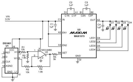
This white LED driver circuit operates up to four white LEDs in parallel from a 3.3V power source, adjusting the total LED current from 1mA to 106mA in 64 steps of 1dB each. The brightness control of the LEDs...
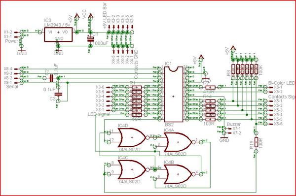
A "Steady Hands Game" was developed to meet the requirement for a cub-scout event. Initially prototyped on a homework board, a more permanent version of the game was created for educational purposes. The final version features a wand (black)...
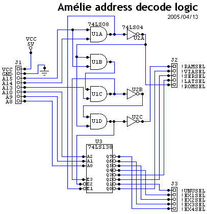
The ROM is mapped at address &F000, which in binary is %1111 0000 0000 0000. This indicates that when accessing the ROM, the address lines A12, A13, A14, and A15 will always be high. Consequently, the I/O device selections...
An 8051 microcontroller-based electronics project that demonstrates the creation of an automated car parking system. This project features a multi-floor parking structure with a lift that transports cars to designated parking areas based on the occupancy status of the...
This is another kit in our self-sufficiency range. We also have a 12v fluoro inverter kit for those who need to operate 20watt to 40watt fluorescent lamps from a 12v supply. We will be introducing a number of kits...