
Solar Charger circuits
The described circuit operates as a blocking oscillator, utilizing a single transistor to generate high-voltage spikes suitable for charging a 12V battery from a solar panel. The primary winding of the transformer consists of 45 turns, while the feedback winding has 15 turns. The circuit is designed to function effectively even when the input voltage is as low as 3.5V, making it versatile for various solar panel configurations, including those that may have damaged cells.
When sunlight intensity fluctuates, the circuit maintains operation by utilizing the collapsing magnetic field in the transformer to generate output voltage spikes. A high-speed diode is employed to rectify these spikes, allowing energy to be transferred efficiently to the battery being charged. The feedback mechanism ensures that the transistor operates in a self-oscillating manner, contributing to the stability and reliability of the charging process.
The inclusion of a 100µF capacitor across the solar panel helps to minimize impedance, maximizing the circuit's performance. The overall design emphasizes low-cost and high efficiency, making it accessible for users seeking to harness solar energy for low-voltage applications. This inverter kit represents a practical solution for those living off-grid or in areas with limited access to traditional power sources, allowing for the enjoyment of electronic devices powered by a 12V supply.This is another kit in our self-sufficiency range. We also have a 12v fluoro inverter kit for those who need to operate 20watt to 40watt fluorescent lamps from a 12v supply. We will be introducing a number of kits for those who have opted to live with 12v energy. With nearly everything electronic capable of operating from a 12v supply, there is no reason why anyone opting to live with a low voltage supply cannot enjoy all the electronic pleasures of those who live in the city.
Some products are not yet available for 12v operation but inverters are available from 100watts to 4kw. he problem with charging a battery from a solar panel is the SUN! It doesn't shine all the time and clouds get in the way! Our eyes adjust to the variations in the strength of the sun but a solar panel behaves differently. As soon as the sun loses its intensity, the output from a solar panel drops enormously. No only does the output current fall, but the output voltage also decreases. Many of the solar panels drop to below the 13.6v needed to charge a 12v battery and as soon as this occurs, the charging current drops to ZERO. This means they become useless as soon as the brightness of the sun goes away. Our project cannot work miracles but it will convert voltages as low as 3.5v into 13.6v and keep delivering a current to the battery.
Obviously the current will be much lower than the maximum, when the sun "half-shines" but the inverter will take advantage of all those hours of half-sun. At least you know it will be doing its best ALL THE TIME. The other advantage of the inverter is the cost of the panel. You don't have to buy a 12v panel. Almost any panel or set of solar cells will be suitable. You can even use a faulty 12v panel. Sometimes a 12v panel becomes damaged or cracked due to sun, rail, heat or shock. If one or two of the cells do not output a voltage (see below on how to fix faulty panels) the cells can be removed (or unwired) and the gap closed up.
This will lower the output voltage (in fact it may increase the voltage - the faulty cells may have reduced the output to zero) but the inverter will automatically adjust. The circuit is a single transistor oscillator called a feedback oscillator, or more accurately a BLOCKING OSCILLATOR.
It has 45 turns on the primary and 15 turns on the feedback winding. There is no secondary as the primary produces a high voltage during part of the cycle and this voltage is delivered to the output via a high-speed diode to produce the output. The output voltage consists of high voltage spikes and should not be measured without a load connected to the output.
In our case, the load is the battery being charged. The spikes feed into the battery and our prototype delivered 30mA as a starting current and as the battery voltage increased, the charging current dropped to 22mA. The transistor is turned on via the 1 ohm base resistor. This causes current to flow in the primary winding and produce magnetic flux. This flux cuts the turns of the feedback winding and produces a voltage in the winding that turns the transistor ON more.
This continues until the transistor is fully turned ON and at this point, the magnetic flux in the core of the transformer is a maximum. But is is not EXPANDING FLUX. It is STATIONARY FLUX and does not produce a voltage in the feedback winding. Thus the "turn-on" voltage from the feedback winding disappears and the transistor turns off slightly (it has the "turn-on effect of the 1 ohm resistor).
The magnetic flux in the core of the transformer begins to collapse and this produces a voltage in the feedback winding that is opposite to the previous voltage. This has the effect of working against the 1 ohm resistor and turns off the transistor even more. The transistor continues to turn off until it is fully turned off. At this point the 1 ohm resistor on the base turns the transistor on and the cycle begins. At the same time, another amazing thing occurs. The collapsing magnetic flux is producing a voltage in the primary winding. Because the transistor is being turned off during this time, we can consider it to be removed from the circuit and the winding is connected to a high-speed diode.
The energy produced by the winding is passed through the diode and appears on the output as a high voltage spike. This high voltage spike also carries current and thus it represents ENERGY. This energy is fed into the load and in our case the load is a battery being charged. The clever part of the circuit is the high voltage produced. When a magnetic circuit collapses (the primary winding is wound on a ferrite rod and this is called a magnetic circuit), the voltage produced in the winding depends on the QUALITY of the magnetic circuit and the speed at which it collapses.
The voltage can be 5, 10 or even 100 times higher than the applied voltage and this is why we have used it. This is just one of the phenomenon's of a magnetic circuit. The collapsing magnetic flux produces a voltage in each turn of the winding and the actual voltage depends on how much flux is present and the speed of the collapse.
The only other two components are the electrolytics. The 100u across the solar panel is designed to reduce the impedance of the panel so that the circuit can work as hard as possible. The circuit is classified as very low impedance. The low impedance comes from the fact the primary of the transformer is connected directly across the input during part of the cycle.
The resistance of the primary is only a fraction of an ohm and its impedance is only a few ohms as proven by the knowledge that it draws 150mA @ 3.2v. If a battery is connected to the circuit, the current is considerably higher. The 150mA is due to the limitation of the solar panel. The aim of this project is to achieve a 13.6v supply at the lowest cost. That's why the project has been released as a kit. The equivalent in made-up form is 3 times more expensive yet doesn't have some of the features we have incorporated in our kit.
We have used a more efficient output circuit than the closest rival design and the driver transistor is the latest "low-voltage" type. These two factors increased the efficiency by 20% over the rival. 🔗 External reference
Related Circuits
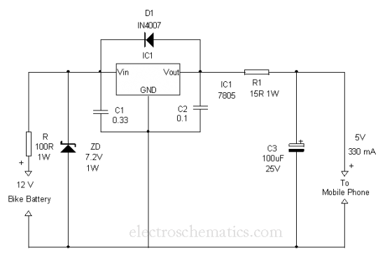
This is a simple and easy method to extract current from a motorcycle battery to charge a mobile phone. Most mobile phone battery packs consist of three 1.2 V cells. To effectively tap current from a motorcycle battery for mobile...
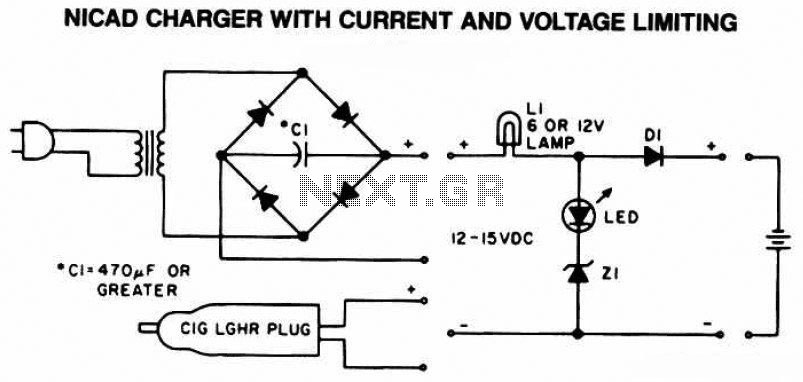
The following diagram is the schematic of a Ni-CAD battery charger circuit, which includes current and voltage limiting features to extend the battery's lifespan. The lamp L1 will illuminate brightly, and the LED will be off when the battery...
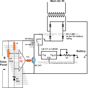
The automatic changeover relay circuit was requested by Mr. Karimulla Baig. The circuit is designed to charge a connected battery at a constant current using power from a solar panel. In the absence of solar energy, such as during...
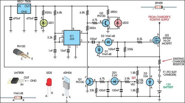
Most commercially available car battery chargers should not be connected to the battery for extended periods, as this can lead to overcharging and subsequent battery damage. This add-on circuit is connected in series with the battery being charged and...
The circuit is actually a half-wave rectifier. It only charges the battery on every half cycle. The plug pack doesn't like this as it leaves residual flux in the core of the transformer and causes it to overheat. But...

The design of solar panel systems with a lead-acid buffer battery is typically configured to ensure that the battery remains charged even during periods of limited sunlight. Solar panel systems integrated with lead-acid buffer batteries are designed to optimize energy...
Warning: include(partials/cookie-banner.php): Failed to open stream: Permission denied in /var/www/html/nextgr/view-circuit.php on line 713
Warning: include(): Failed opening 'partials/cookie-banner.php' for inclusion (include_path='.:/usr/share/php') in /var/www/html/nextgr/view-circuit.php on line 713