
MAX1573 white led driver electronic project schematic

The LED driver circuit is designed to provide precise control over the brightness of multiple white LEDs, making it suitable for applications requiring variable lighting conditions. The use of a 3.3V source ensures compatibility with low-voltage systems, while the ability to adjust the current in 64 discrete steps allows for fine-tuning of brightness levels.
Operational amplifier U2 plays a critical role in the feedback loop, ensuring that the output current remains stable and proportional to the input from the digital potentiometer U1. The logarithmic taper of the digital potentiometer allows for a more natural perception of brightness changes, as human eyes perceive light intensity on a logarithmic scale.
The fixed SET voltage of 0.6V is a key parameter in determining the performance of the circuit. By adjusting the resistance of R5, the maximum current flowing through the LEDs can be tailored to the specific requirements of the application, allowing for flexibility in LED selection and desired brightness levels. This adaptability makes the circuit ideal for various lighting applications, including decorative lighting, indicator lights, or even task lighting where adjustable brightness is essential.
In summary, this LED driver circuit combines a low-voltage operation with advanced brightness control features, ensuring efficient and effective LED management for a wide range of electronic applications.This white led driver circuit circuit drives as many as four white LEDs in parallel from a 3. 3V source, and adjusts the total LED current from 1mA to 106mA, in 64 steps of 1dB each. To control the LED brightness, op amp U2 monitors the difference between the high-side voltage and the wiper voltage of digital potentiometer U1. The op amp then mult iplies that voltage by a gain to set the maximum output current. Zero resistance at the pot`s W1 terminal corresponds to minimum LED current, and therefore minimum brightness. Because the SET voltage is fixed (at 0. 6V), any voltage change at the left side of R5 changes ISET, and the resulting change in LED currents changes their brightness level.
R5 sets the maximum LED current: R5 = 215x0. 6/ILED(Desired) (ILED is the current through one LED). U1 integrated circuit is a digital potentiometer with logarithmic taper and an analog-voltage wiper for which each tap corresponds to 1dB of attenuation between H1 and W1 (pins 11 and 9). 🔗 External reference
Related Circuits
Its based on inductive pickup and very easy to install. Have a look at the pic. (remove LED and connect transistor collector to pin4). I hope it will exactly suits to your tachometer. More: I found your PIC project...
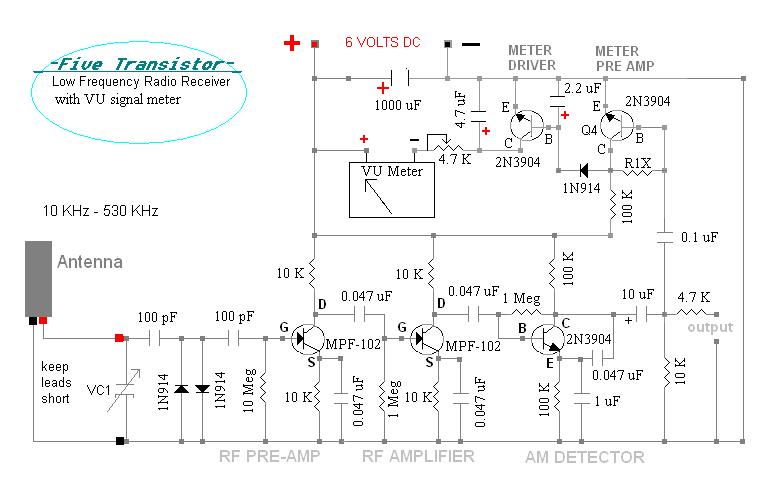
This radio receiver, constructed on a wooden base, utilizes only five transistors to receive longwave beacons and VLF beacons, depending on the connected antenna unit. It incorporates the AMVC-384 capacitor along with one of the "C" antennas. The unit,...
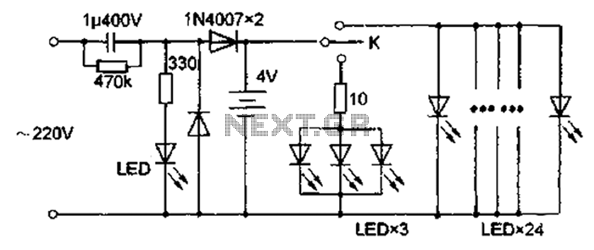
The circuit diagram depicted in Figure 5 illustrates a system for charging a lead-acid battery using 220V AC power. The circuit employs a capacitor, buck converter, and diode rectifier for this purpose. A red LED indicates the charging status....
Advanced power control systems utilize electronic components such as thyristors for power switching, motor control, and other applications. These systems are involved in inverter design, lamp dimming, and speed control of motors. Triacs are the most commonly used semiconductor...
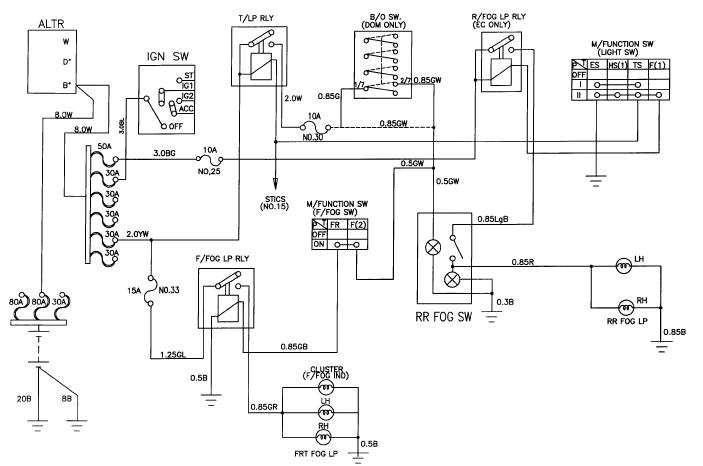
The schematic for the front and rear fog lamps of the Daewoo Korando is illustrated in the accompanying figure. It details the connections and wiring between various components of the fog lamp system, including the alternator, ignition switch, taillamp...
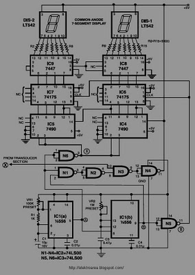
This circuit is designed to display the speed of a vehicle in kilometers per hour (km/h). An opaque disc is mounted on the spindle connected to the front wheel of the vehicle. The disc features evenly spaced holes along...