
Solar Panel Based Charger And Small LED Lamp
The described photovoltaic module circuit provides a versatile solution for charging different types of batteries using solar energy. The inclusion of protective components such as diodes ensures the safety and longevity of both the solar panel and the batteries being charged. The use of an ammeter allows for monitoring of the charging current, which is essential for maintaining optimal charging conditions.
For lead-acid battery charging, the circuit's design emphasizes the importance of using pulsating DC to prevent sulfation on the battery plates. This is a critical consideration, as lead-acid batteries can suffer from reduced efficiency and lifespan if not charged correctly. The requirement to switch to a standard pulsating DC charger weekly is a practical approach to maintaining battery health.
The charging circuits for Ni-Cd and Li-ion batteries incorporate voltage regulators to ensure stable and appropriate charging currents. The 7806 and 7805 voltage regulators are widely used in electronic circuits for their reliability and ease of use. By configuring these regulators correctly, the circuit can provide the necessary current while preventing overcharging, which is crucial for maintaining battery performance and safety.
The LED-based lamp circuit demonstrates a straightforward application of the power generated by the solar panel. By using parallel connections for the LEDs, the circuit minimizes complexity while maximizing light output. The choice of using rechargeable batteries for this application aligns with the overall goal of sustainability and energy efficiency.
In conclusion, this solar-powered charging circuit not only offers a cost-effective solution for battery charging but also promotes the use of renewable energy sources, contributing to reduced electricity costs and environmental sustainability. The design considerations and component selections ensure that the circuit operates efficiently and safely across different battery types.You can save on your electricity bills by switching to alternative sources of power. The photovoltaic module or solar panel described here is capable of delivering a power of 5 watts. At full sunlight, the solar panel outputs 16. 5V. It can deliver a current of 300-350 mA. Using it you can charge three types of batteries: lead acid, Ni-Cd and Li-io n. The lead-acid batteries are commonly used in emergency lamps and UPS. The working of the circuit is simple. The output of the solar panel is fed via diode 1N5402 (D1), which acts as a polarity guard and protects the solar panel. An ammeter is connected in series between diode D1 and fuse to measure the current flowing during charging of the batteries.
As shown in Fig. 1, we have used an analogue multimeter in 500mA range. Diode D2 is used for protection against reverse polarity in case of wrong connection of the lead-acid battery. When you connect wrong polarity, the fuse will blow up. For charging a lead-acid battery, shift switch S1 to on` position and use connector A. ` After you connect the battery, charging starts from the solar panel via diode D1, multimeter and fuse.
Note that pulsating DC is the best for charging lead-acid batteries. If you use this circuit for charging a lead-acid battery, replace it with a normal pulsating DC charger once a week. Keep checking the water level of the lead-acid battery. Pure DC voltage normally leads to deposition of sulphur on the plates of lead-acid batteries. For charging Ni-Cd cells, shift switches S1 and S3 to on` position and use connector B. ` Regulator IC 7806 (IC1) is wired as a constant-current source and its output is taken from the middle terminal (normally grounded).
Using this circuit, a constant current goes to Ni-Cd cell for charging. A total of four 1. 2V cells are used here. Resistor R2 limits the charging current. For charging Li-ion battery (used in mobile phones), shift switches S1 and S2 to on` position and use connector C. ` Regulator IC 7805 (IC2) provides 5V for charging the Li-ion battery. Using this circuit, you can charge a 3. 6V Li-ion cell very easily. Resistor R3 limits the charging current. Fig. 2 shows the circuit for a small LED-based lamp. It is simple and low-cost. Six 10mm white LEDs (LED2 through LED7) are used here. Just connect them in parallel and drive directly by a 3. 6V DC source. You can use either pencil-type Ni-Cd batteries or rechargeable batteries as the power source. Assemble the circuit on a general-purpose PCB and enclose in a small box. Mount RCA socket on the front panel of the box and wire RCA plug with cable for connecting the battery and LED-based lamp to the charger.
🔗 External reference
Related Circuits
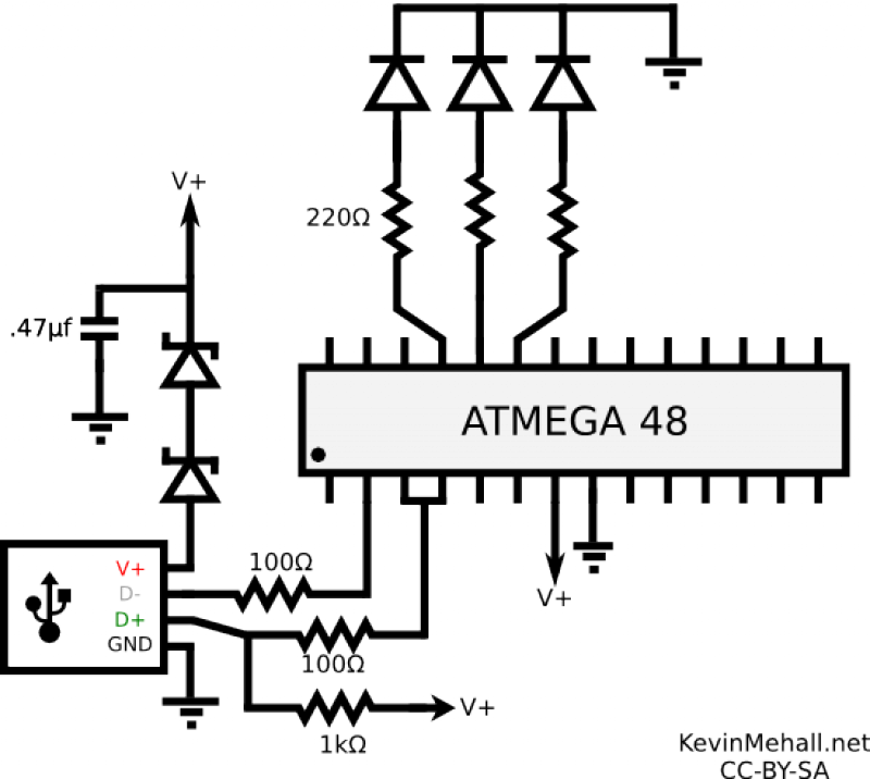
The article on the RGB LED fader has been one of the most visited articles on this blog. Since its publication, another microcontroller-based RGB LED project has been designed and built, this time controlling the colors from a computer...
The car's small lamp and headlight can drain the battery if they are not turned off, leading to engine starting issues. A simple circuit, developed around 1980, can prevent this problem. It includes a series circuit with a diode...
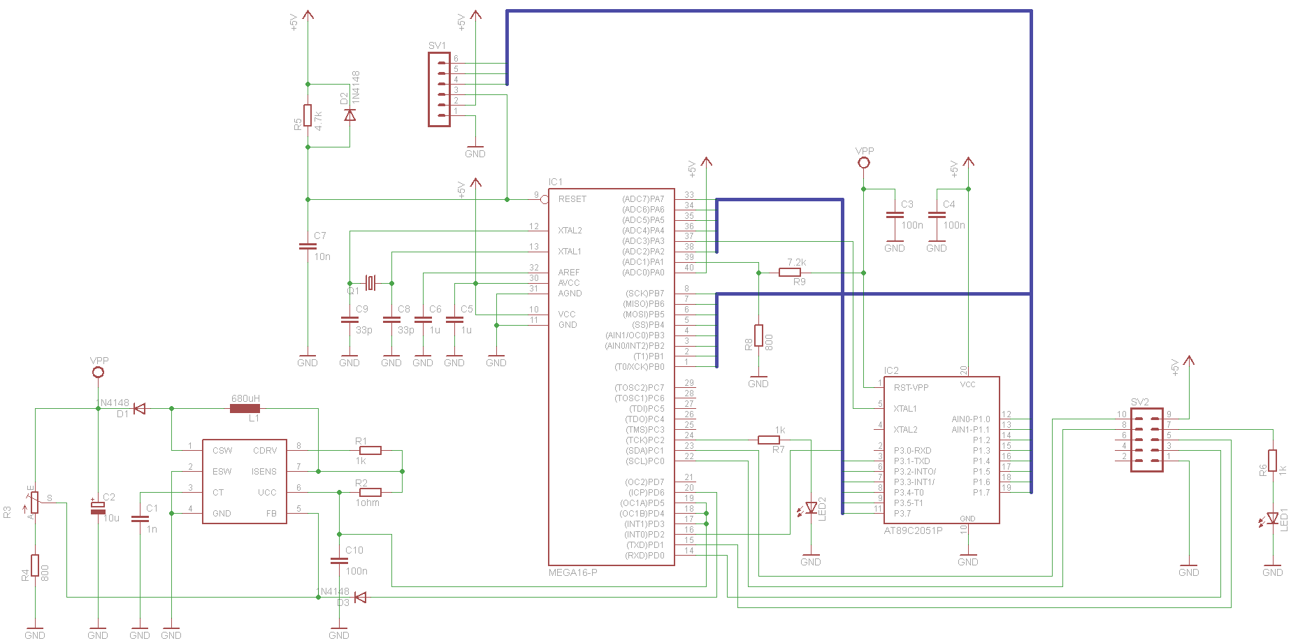
This project has been set aside for several years. It was initially intended for programming old 8051 microcontrollers, which have since become obsolete. The project was recently revisited due to the need for a programmer for the Atmel Xmega...
Upon entering the password, the application, in this case "LED," will illuminate. In this digital locking system project, the interfacing of a keypad and a 16x2 LCD with a microcontroller will be explored, along with the accompanying code. This...
This single white LED torch can be housed in an empty glue stick tube and has a long rechargeable battery life. The proposed circuit design features a compact LED torch that utilizes a single white LED as the primary light...
The circuit is a comparator that can measure the voltage of a car battery in steps of 1 Volt. The voltage is determined after comparing the voltage of the battery, which is applied to the inverting inputs of amplifiers,...