
LED Voltmeter for Cars
R1=1K2 R6=10K D2-3-4-5=LED R2-3-4=680R R7-8-9-10=1K IC1=LM324 R5=15K D1=5V6 /0.5W Zener RV1=10K trimmer
The described circuit functions as a voltage comparator, utilizing an LM324 integrated circuit, which contains four operational amplifiers. The primary purpose of this comparator circuit is to monitor the voltage level of a car battery, providing visual feedback through the use of LEDs that indicate the battery's voltage status.
The Zener diode (D1), specified as 5.6V with a maximum power rating of 0.5W, serves as a stable reference voltage source. This stability is crucial for accurate voltage comparisons, especially in automotive applications where temperature variations can affect performance. The reference voltage generated by the Zener diode is applied to the non-inverting input of the operational amplifier, while the battery voltage is fed into the inverting input.
Resistors R1 (1.2 kΩ), R2, R3, and R4 (all 680 Ω) are configured to set the gain of the operational amplifier and to ensure that the output is appropriately scaled for the LEDs. The variable resistor (RV1) at 10 kΩ allows for fine-tuning of the reference voltage, enabling the user to calibrate the circuit for different battery types or conditions.
The output from the LM324 is connected to four LEDs (D2, D3, D4, D5), which provide a visual indication of the battery voltage level. Each LED corresponds to a specific voltage range, illuminating sequentially as the battery voltage increases. Resistors R6 (10 kΩ) and R7 to R10 (all 1 kΩ) are used to limit the current through the LEDs, ensuring they operate within safe limits and prolonging their lifespan.
Overall, this circuit effectively combines precision voltage measurement with a user-friendly visual output, making it a practical solution for monitoring automotive battery health.The circuit, is a comparator, can measure with step of 1Volt, the voltage of battery of car. The clue of voltage become after comparison of voltage of battery, that is applied in the inverting inputs of amplifiers, with voltages of reference that are produced by a Zener D1, the value of which is such so that it present good thermic stability. With the RV1, we regulate the gradation of voltage that we want. The optical clue become from four Led. R1=1K2 R6=10K D2-3-4-5=LED R2-3-4=680R R7-8-9-10=1K IC1=LM324 R5=15K D1=5V6 /0.5W Zener RV1=10K trimmer 🔗 External reference
Related Circuits
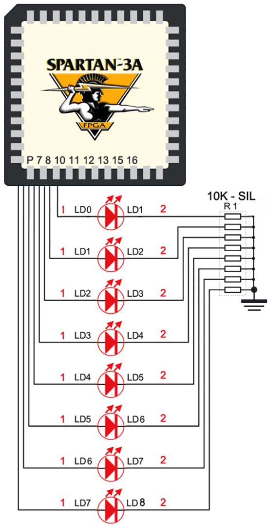
The Spartan-3an board features eight LEDs connected to FPGA I/O pins. The cathode of each LED is connected to ground through a 330-ohm resistor. To illuminate a specific LED, the corresponding FPGA control signal must be set to High. The...

The entire series of TTL monostable multivibrators lacks sufficient speed, prompting the need for an ECL voltage swing that accommodates a wide range of small power requirements. This necessitates the use of F series circuits, which offer fast transition...
If we have a lot of parallel telephones on a telephone line, we needed a unit that will have the possibility of showing if somebody of the telephone has raised the earphone. Our this possibility give the circuit. The...

This schematic illustrates a peak-reading diode voltmeter that is powered by two amplification stages. A 100 µF capacitor is utilized to create a substantial time constant, which ensures effective damping of the meter. The restricted differential output voltage, combined...
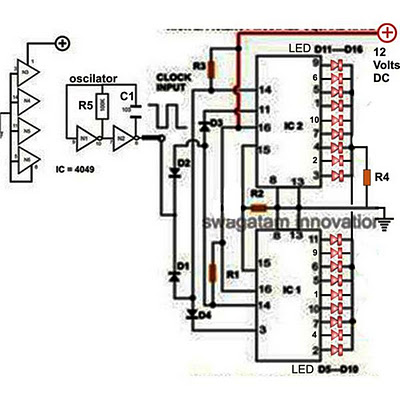
Decorative lights arranged in various moving patterns are visually appealing and have gained significant popularity in today's world. While more complex lighting arrangements may require the use of microcontroller ICs, simpler yet captivating light effects can be generated using...

This general-purpose signal source is highly effective for signal-tracing applications. The output level is adjustable, exceeding 1 Vrms into a 50 Ω load. It is compatible with nearly any crystal in the 1 to 15 MHz frequency range. Q1...