
SOLAR REVOLVER

The project involves utilizing a 1381 series voltage regulator, specifically the 1381wr variant, to control the operation of a 74AC240 octal buffer/driver. The 1381wr is capable of providing a stable output voltage, which is essential for enabling the 74AC240 chip. The 74AC240 functions as a buffer, allowing for the driving of multiple outputs while isolating the input signal from the load.
In this design, the chip enable feature of the 74AC240 is utilized to control when the device is active. The integration of spare inverters into the circuit design enhances the overall functionality, allowing for more complex operations and interactions within the solar roller system. The intention was to create a simple yet effective method of enabling the chip while minimizing power consumption and maximizing efficiency.
The initial concept of using the 1381wr SE to enable the 74AC240 was reconsidered due to the potential for over-specification, as the 1381wr is designed for high-current applications, such as driving motors. Instead, a more suitable design was proposed, which incorporates a simplified version of the Miller Engine. This approach allows for a more tailored solution that meets the specific requirements of the solar roller, ensuring that the energy management is optimized for solar applications.
The final design should incorporate necessary components, including capacitors for stability and filtering, as well as resistors to set appropriate thresholds for the chip enable function. This schematic will provide a robust framework for the solar roller, ensuring reliable operation and efficient energy use in various environmental conditions.How would you use an SE with a chip enable? Good question and well one thing leads to another and before you know it a new solar roller is born. The design started out as a simple example of using the 1381wr SE to enable a 74AC240 chip. But with all those spare inverters looking for something to do, the SE kind of got integrated with a whole new solar roller design.
The original intention was to use a variation of the 1381wr SE to enable a 74AC240 chip, but that SE is designed to drive a motor directly and would be overkill. The simple Miller Engine would suitable but I opted for a new 1381 SE design in the Solar Re 🔗 External reference
Related Circuits
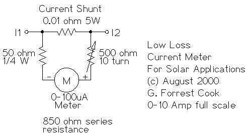
This circuit is used to measure the current from a solar panel. It has very low power loss for currents in the 0-10A range. It also works as a general purpose DC current meter. The circuit can be used...
The large servos shown alongside a Nokia 3310 mobile phone provide a reference for scale. The servo arms measure 12 cm in length, making them suitable for lifting a bank of solar panels. The local Model Aerodrome in Seaside...
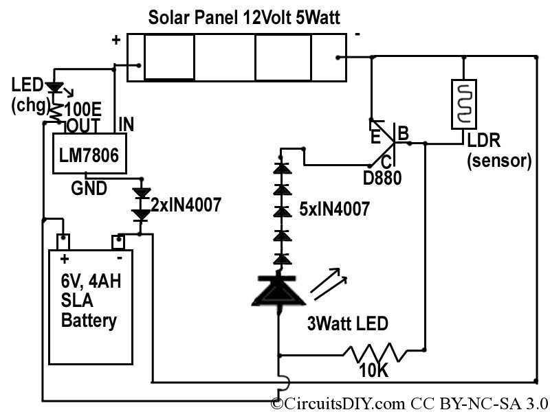
This document discusses a simple solar LED circuit. Solar panels range from 12 volts and 3 watts to larger sizes. To store energy, a 12-volt battery is required. The preferred choice is a sealed lead-acid (SLA) sealed maintenance-free (SMF)...
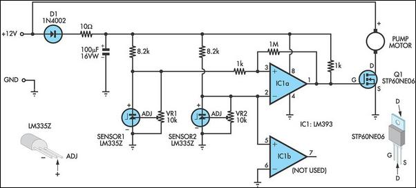
This circuit optimizes the operation of a solar hot water system. When the water in the solar collector is hotter than the storage tank, the pump runs. The circuit comprises two LM335Z temperature sensors, a comparator, and a MOSFET....
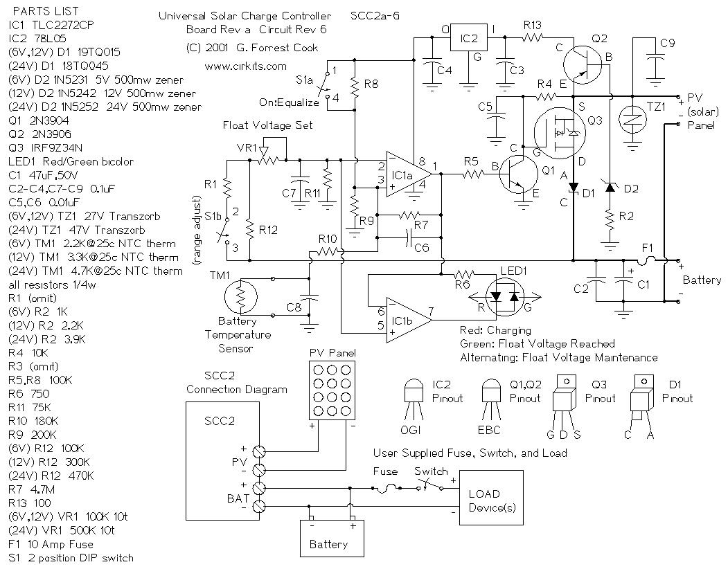
The SCC2 is a solar charge controller designed to manage the power transfer from a photovoltaic panel to a rechargeable battery. It includes a straightforward setup process utilizing a single potentiometer for adjusting the float voltage, an equalization function...
Construct a low-cost and relatively simple robot that activates whenever a desk lamp is illuminated. The design does not incorporate any sensors. This robot can be designed using basic electronic components to create a simple activation mechanism based on light...