
Solar to 6V Batt to LED emergency light circuit
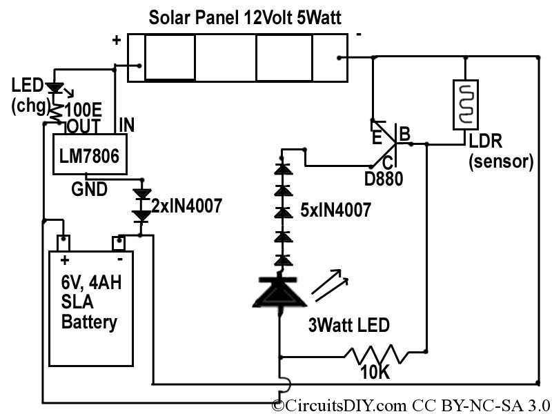
In the provided circuit diagram, the 12-volt supply from a 5-watt solar panel is regulated by an LM7806 integrated circuit (I/C) to charge a 6-volt battery. Since 6-volt batteries charge at 7.2-7.5 volts, two forward-biased IN4007 diodes are added to set a reference level, creating a zener breakdown at 1.2 volts, which results in an output voltage of 7.2 volts. This configuration allows for a charging current of approximately 400 mA (5/12), which is a suitable level, being C/10 of the battery's capacity, thus preventing overcharging.
For the LED driving unit, a similar approach is used to reduce the voltage. The voltage of the 6-volt SMF battery is typically around 6.4-6.6 volts. Five forward-biased IN4007 diodes are connected in series to lower the voltage by approximately 3 volts, providing around 3.5 volts to the LED. If increased brightness is desired, one of the diodes can be bypassed to raise the voltage by 0.6 volts. The driver transistor employed is the D880, a readily available NPN transistor with high current ratings. The base of the transistor is biased through a 10K resistor connected to the +6V rail, while it is reverse-biased through a light-dependent resistor (LDR) to ground. When light strikes the LDR, the transistor remains unsaturated; conversely, in darkness, the transistor conducts. The total cost for components in this circuit is estimated to be between 30-35 rupees. A printed circuit board (PCB) can also be designed instead of using a veroboard for assembly.
This solar LED circuit provides an efficient and cost-effective solution for lighting applications, utilizing renewable energy and simple electronic components to achieve reliable operation. The design ensures that the battery is charged without the risk of overcharging and that the LED operates effectively based on ambient light conditions.Today we discuss about a simple solar LED circuit. We know that solar panels comes from 12Volt 3watt to larger sizes. So, for storing energy, we need a 12Volt battery. As we don`t want jhamela`, we prefer SLA SMF batteries. 12Volt SMF batteries comes around 650-700 rupees, while 6Volt SMF batteries comes in 150-200 rupees, commonly known as charge r battery. These have 4AH rating at 6Volt. That`s of the source and storage, now we think about the output. Yes, we will be using a LED of high leumens of course. 1Watt or 3Watt LED requires 3. 5-4Volt forward voltage to glow at full intensity. We also need to provide a way that the circuit senses light and turns on the LED whenever there is darkness(night). This below circuit does above all steps in a simple manner of voltage regulation. If we have used voltage conversion technology, it would be more efficient but that would increase circuit`s complexity and cost.
So, the circuit diagram below. In the diagram, we can see 12Volt supply from solar panel(5Watt) is regulated by LM7806 I/C to charge 6Volt battery. Since 6Volt batteries charge at 7. 2-7. 5Volt, we added two forward biased IN4007 diode to reference level, so that the pair makes a zener breakdown at 1.
2Volts, making the output at 7. 2Volts. That voltage charges battery at maximum 5/12=400ma(appx) which is a good current level, as it is exactly C/10 of that of battery. So, this will never overcharge the battery. Now we come to LED driving unit. Here, we use same logic of forward biased diode to reduce voltage. The battery voltage of 6Volt SMF battery is around 6. 4-6. 6Volts. Here we attach 5 forward biased IN4007 diode to reduce voltage by appx 3Volt, so the LED is fed with around 3.
5Volts. If we require more brightness, we will short any one of the diodes to increase the voltage by 0. 6Volt. The driver transistor here used is D880, we have used it in many circuits, as it is a easily available NPN transistor with high current ratings. We bias the base through a 10K resistor from the +6V rail, and reverse bias it through a LDR to GND. Thus, when there is light on LDR, the transistor will be unsaturated, and vice versa. The total parts expense in this circuit is 30-35 rupees. We can also make a PCB instead of making it on vero. 🔗 External reference
Related Circuits
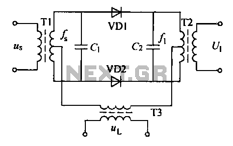
A balanced diode mixer circuit is presented, utilizing two diodes, specifically the 2AP9 model. The circuit operates with a high voltage, causing the diodes to function in an off state, which is also referred to as a diode switch...
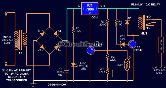
This circuit automates the control of street or porch lights. The automatic lamp controller circuit utilizes a 7806 voltage regulator IC, which can be employed to automate street lights, tube lights, or any other home electrical lighting systems. The...
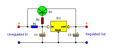
This is a compact and highly functional circuit that can be constructed on a veroboard. Voltage regulators such as the LM708 and LM317 series (among others) may occasionally require a load. The circuit utilizes voltage regulators, which are essential components...
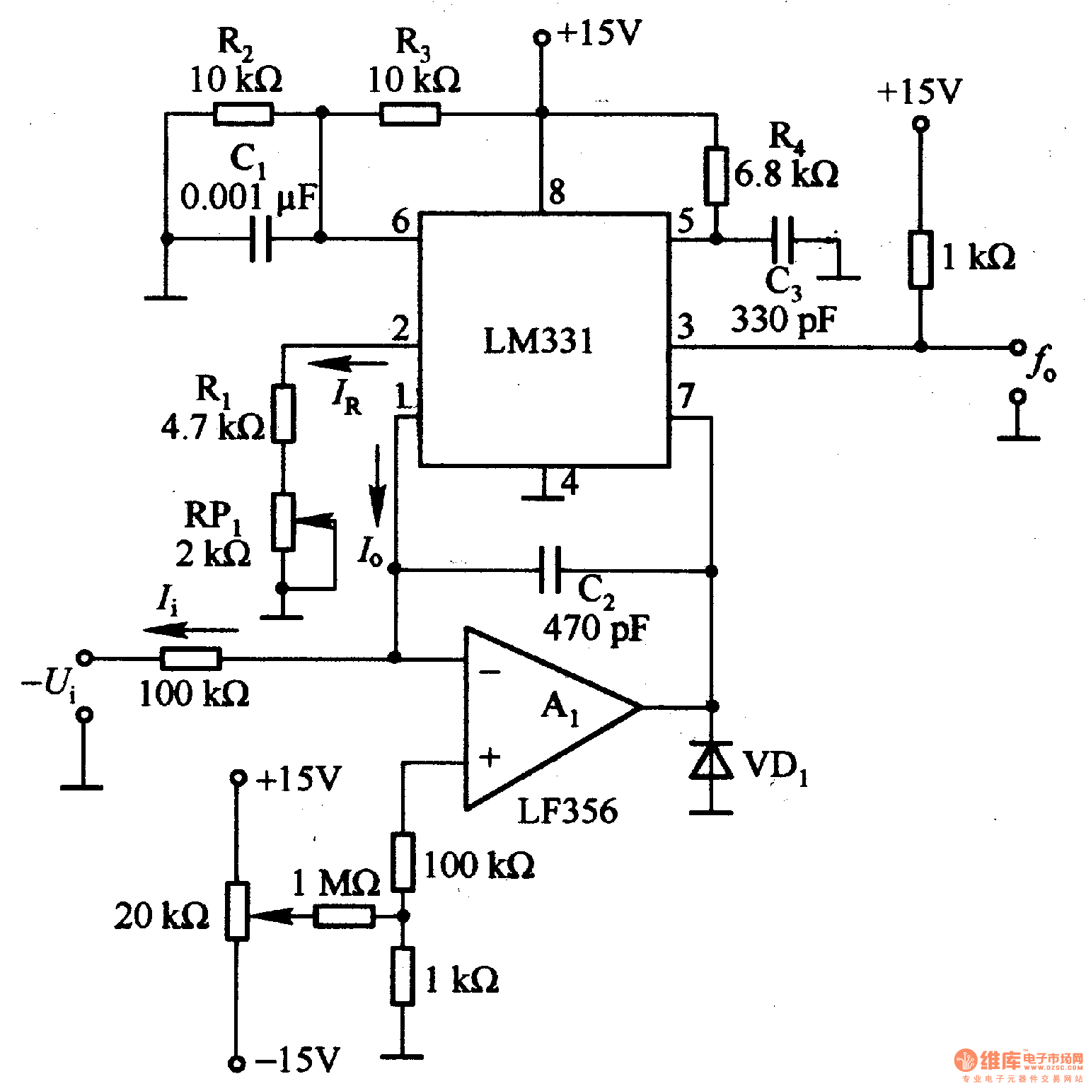
The LM331 is a single voltage-to-frequency conversion integrated circuit (IC) that includes a 1.9 V reference voltage, a current switch, a comparator, and a flip-flop. To expand its operational range, an A1 operational amplifier is added to the circuit....
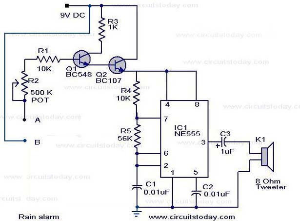
The operation of the rain alarm circuit is explained in detail. The rain alarm project is outlined along with a circuit diagram. The rain alarm circuit is designed to detect the presence of rain and alert users through an audible...
The circuit below demonstrates how to construct a DAQ_LITE device, accompanied by an image of the finished PCB board. It is important to note that the 80mA fuse depicted in the image and the nearby protection diode are recommended...
Warning: include(partials/cookie-banner.php): Failed to open stream: Permission denied in /var/www/html/nextgr/view-circuit.php on line 713
Warning: include(): Failed opening 'partials/cookie-banner.php' for inclusion (include_path='.:/usr/share/php') in /var/www/html/nextgr/view-circuit.php on line 713